Introduction
Table of Contents
The COncurrent Model-based Engineering Tool (COMET) is a Model Based System Engineering tool that implements the ECSS-E-TM-10-25 standard for use in the conceptual design phase of a project. COMET is an open source software (not limited to ESA member states) which is supported and maintained by Starion Group https://www.stariongroup.eu/services-solutions/system-engineering/concurrent-design/cdp4-comet/.
COMET is built on concurrent engineering principles meaning that a centralised repository is used, allowing data to be sent and retrieved directly through the central repository, removing the need for data to be sent individually multiple times. By taking this approach iterations can be made faster and more efficiently allowing a design to emerge in the order of weeks instead of months.
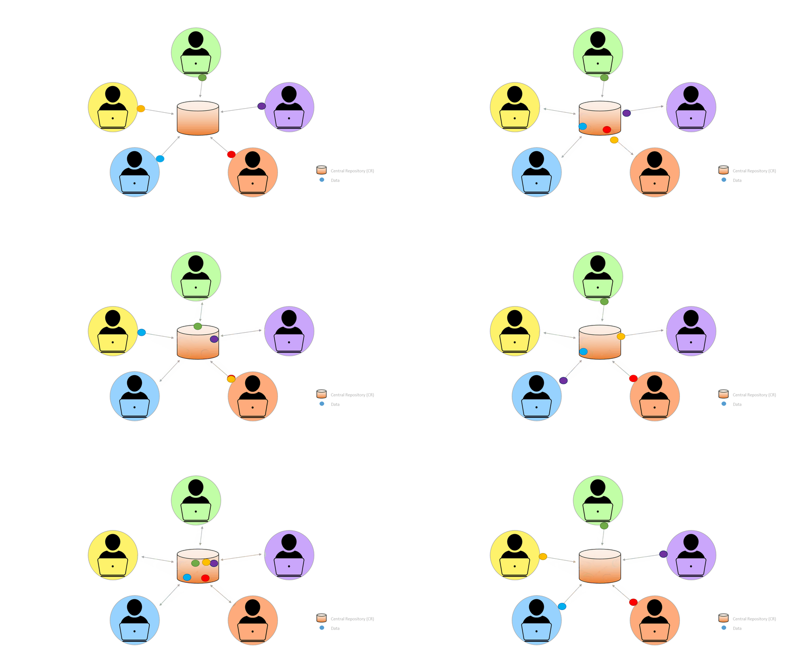
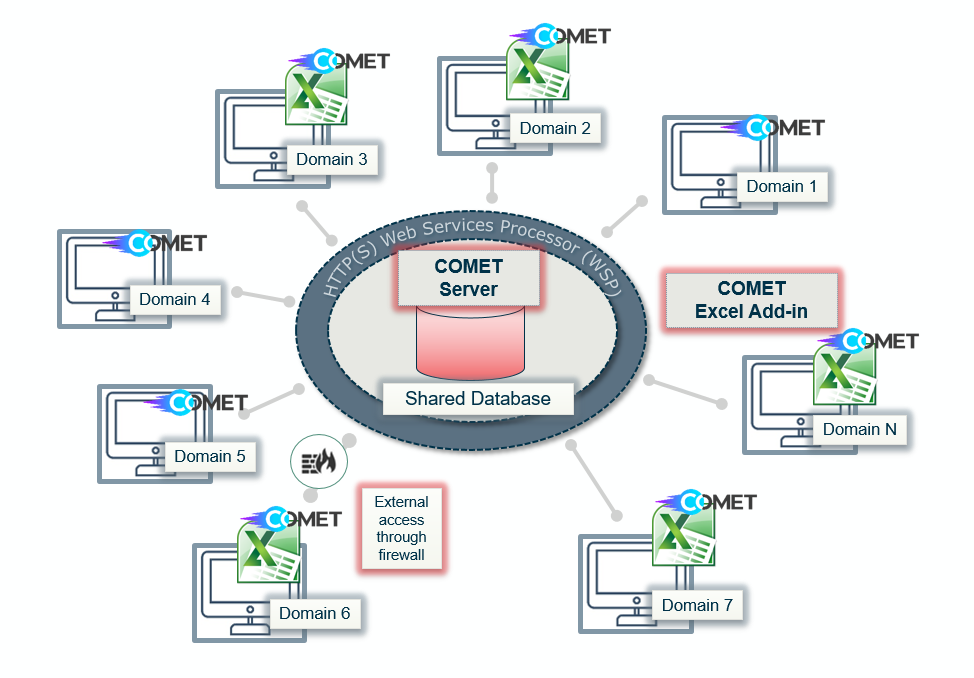
The COMET server acts as the shared data base in the centralised repository which multiple users can access and edit concurrently, allowing for collaborative and distributed engineering. By collecting the data within COMET, all information is captured in a formal way. Each user can both enter data to their own domain and retrieve data entered by other domain users that is relevant to them.
Data in the COMET server can be visualised and interacted with in several ways; through the COMET Application, through the COMET Excel Plugin and by externals through a firewall.
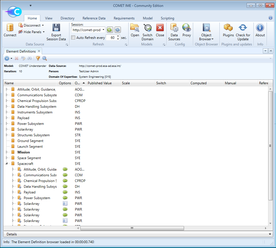
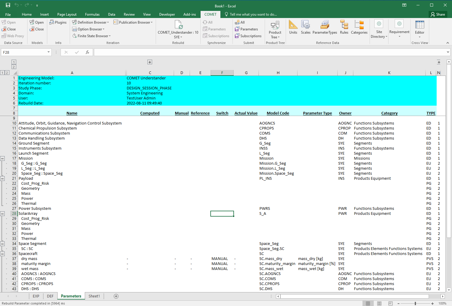
Each project using COMET will use one COMET Study Model for the data exchange. Within this Study Model many different types of information can be contained. This includes:
- Mission parameters
- Orbit parameters
- etc
- System global characteristics
- Total mass at launch
- Spacecraft dimensions
- etc
- Equipment physical characteristics
- Units and associated masses
- Power
- etc
- System performance parameters (to be compared with system requirements)
- Pointing accuracy
- Instrument resolution
- etc
Working with a COMET model
Every mission has a system that is composed of many elements such as equipment, instruments, ground stations, spacecraft etc. All of these elements can be captured in a COMET Study Model where they are defined as Element Definitions. The structure of a mission depends on how the elements of its system are put together. In COMET, this can be achieved by nesting lower level Element Definitions inside higher level Element Definitions, these are defined as Element Usages.
In order to build the mission, experts are required from many different domains, this could, for example, include:
- Instruments
- Power
- Systems
- Mission Analysis
- Cost
- Etc
Defining the system
Functional modelling
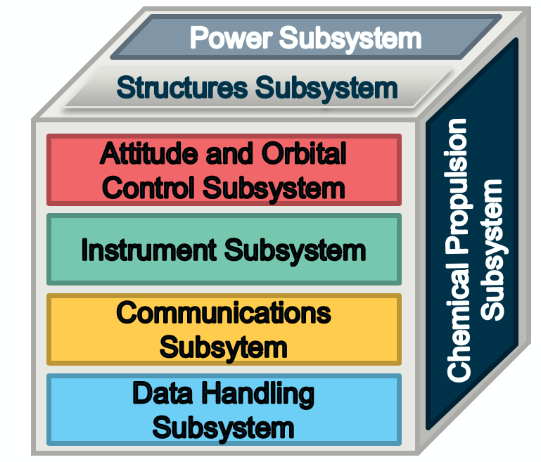
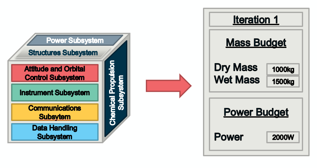
To get a model started, each domain needs to provide an initial estimate of the total subsystem mass and power to allow the first design loop to begin. This initial estimate should be based on previous experience, heritage, etc and does not need to be accurate, just within an order of magnitude.
When a domain is modelled in this way it is a Functional Representation, as the mass and power represent the whole domain not any specific equipment. When a domain is later modelled by individual equipment it is a Product Representation, as the total mass and power is made up from the individual mass and power of the individual equipment. Products should not be placed under a function; therefore equipment (a product) should never be placed inside a subsystem (a function).
From these first estimations the Systems Engineering experts can create an initial mass and power budget that provides the basic information required.
Product modelling
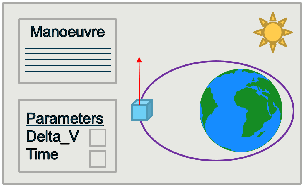
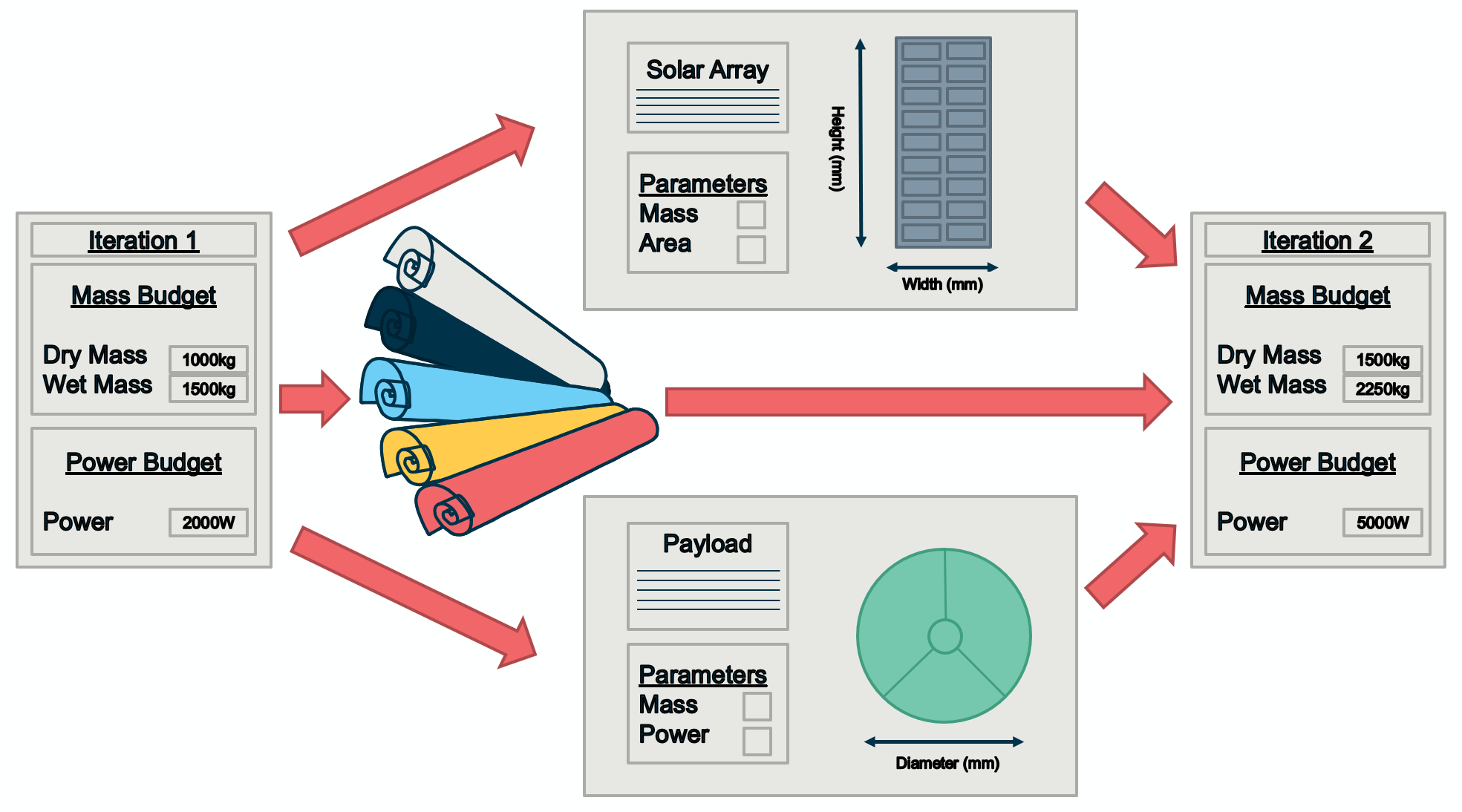
Element Definitions are used to build up the mission. These can be thought of as blueprints, either of generic equipment such as a solar array, of theoretical components such as an orbital manoeuvre or as Functional Representation of a subsystem such as when entering the first estimations of a total subsystem.
For example in COMET a Power expert can create a blueprint for a solar array and a Mission Analysis expert can create a blueprint for an orbital manoeuvre.
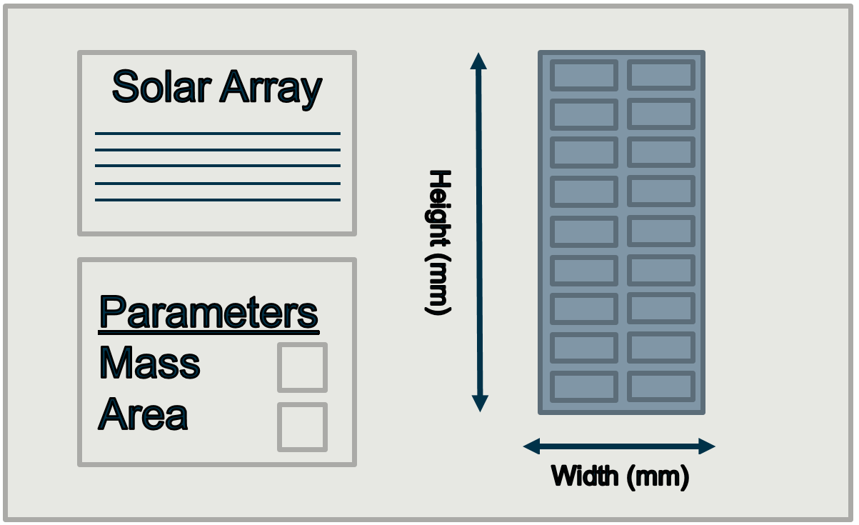
Once the blueprints have been created they are part of the model but they are not yet used in the system. This can be imagined as creating a blueprint only describes how something should be built, but until the blueprint is used the item is not built. By using the blueprints in a specific system, such as using a solar array inside a spacecraft, that blueprint becomes a part of that specific system.
For the solar array example in COMET, the Power expert can use the blueprint for the solar array in the spacecraft to build a solar array onto the spacecraft. This turns the solar array Element Definition into a solar array Element Usage inside the spacecraft Element Definition.
If the spacecraft requires more than one solar array, the blueprint can be added to the system again to create a second solar array in the spacecraft. As the solar array is already described by its blueprint it is not necessary to create another blueprint. In COMET this means one Element Definition can be used to create multiple identical Element Usages.
In the same way as the Power expert created a solar array, the Instruments expert can create their own blueprints for their equipment. The Instrument expert creates a payload blueprint to model the payload and then uses it inside the spacecraft.
As each domain continues to do this, the system slowly builds up into a complete mission. In this example, the spacecraft will go from the structure with a solar array attached, to having the payload attached, until the point at which all domains are included and a complete spacecraft is created.
Iterations
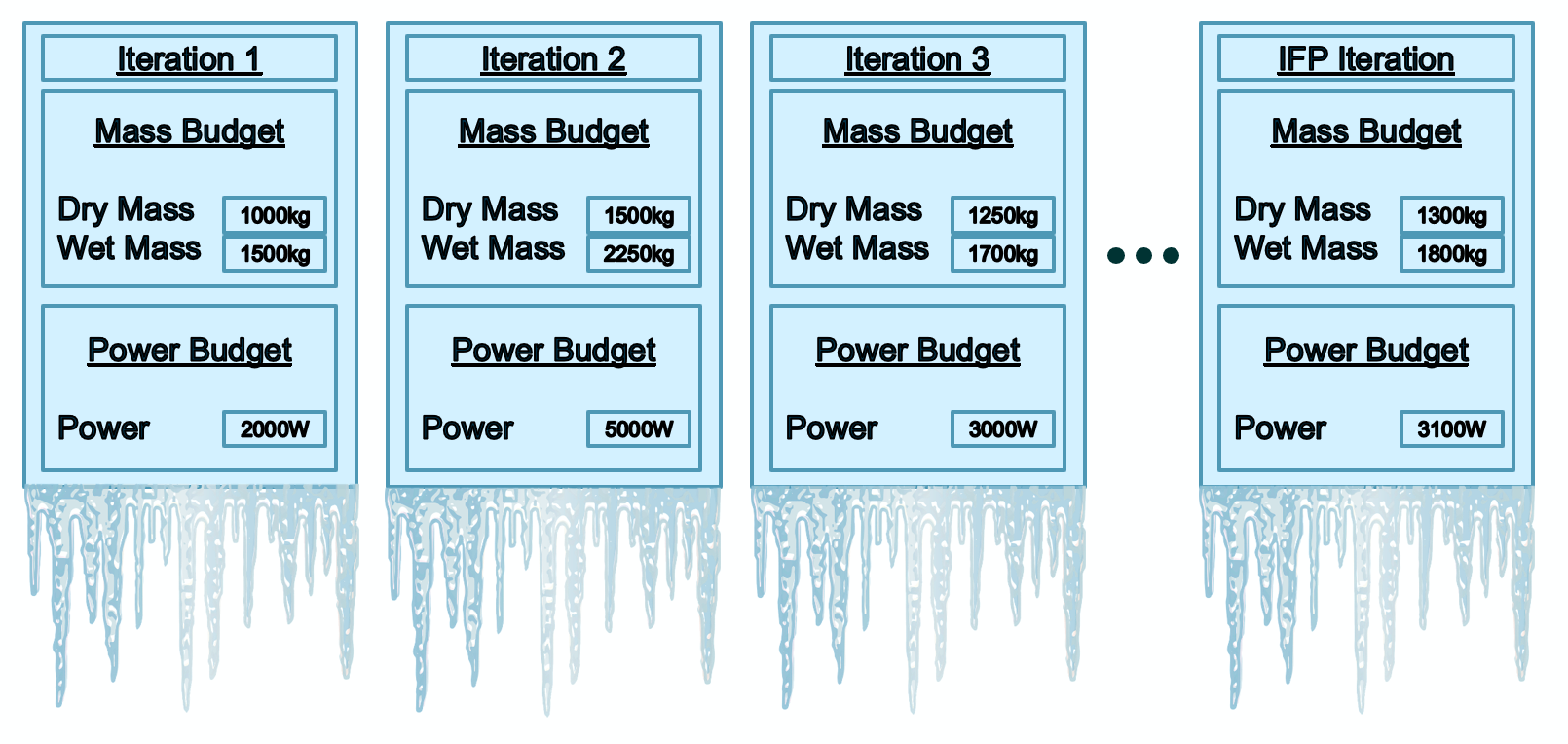
During a CDF study the model will evolve and mature as more analysis and information is gathered. This will mean that the model will have several different iterations over the course of the study with each iteration being more mature than the previous.
The first Iteration will come from the initial Functional Representation of each subsystem.
The second Iteration will be based on initial modelling of the equipment as a Product Representation.
The following Iterations are then created as the model matures further during CDF sessions.
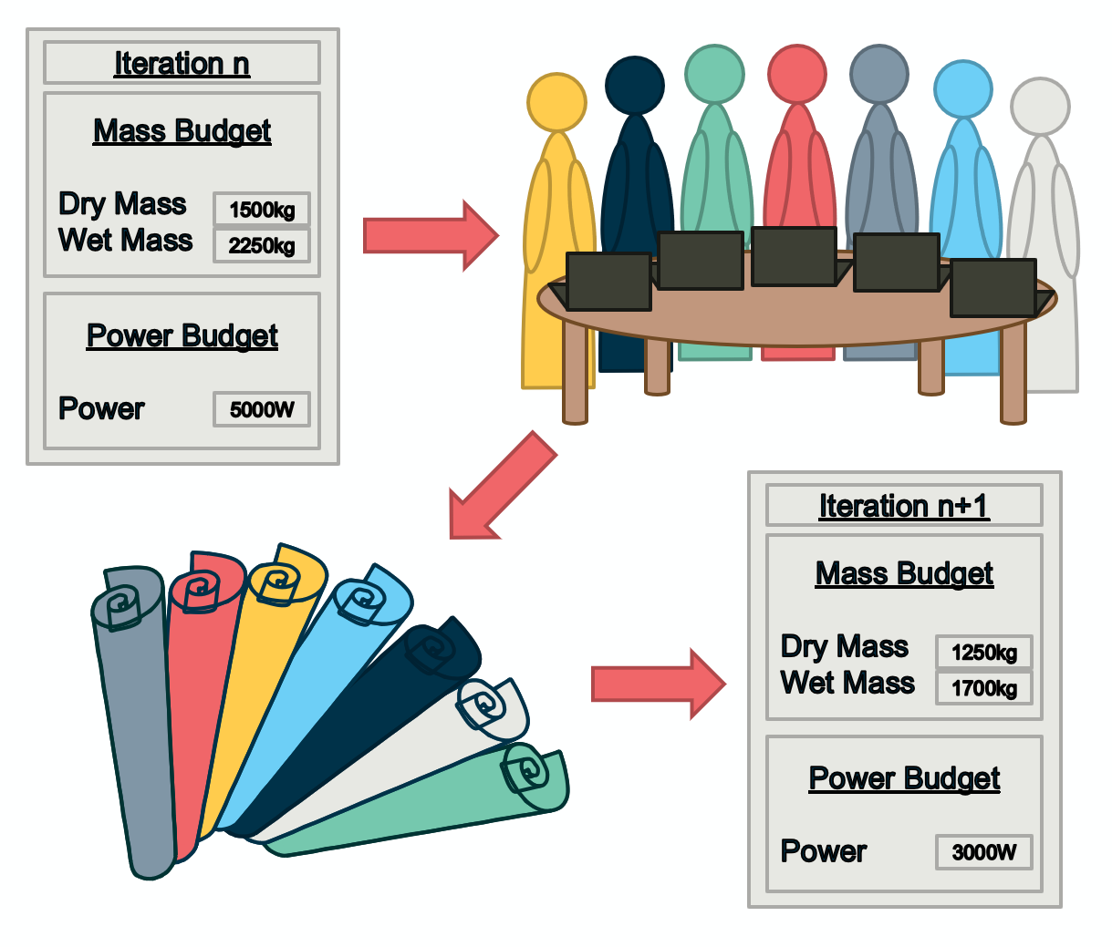
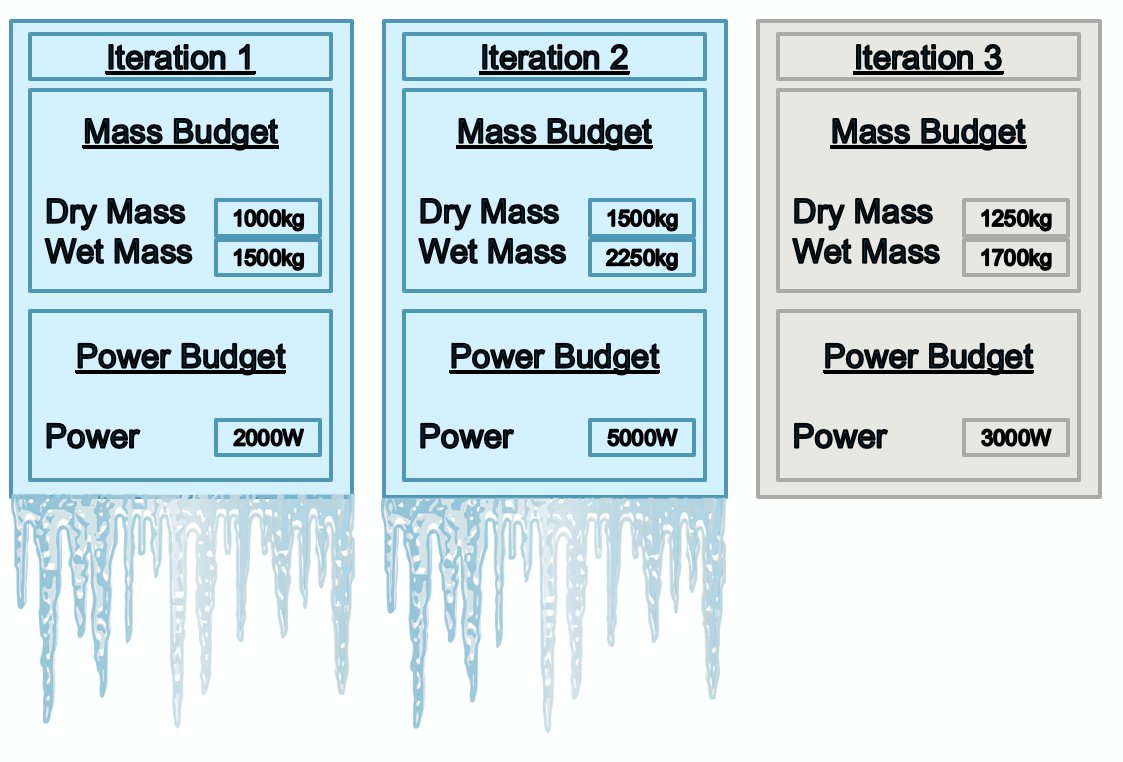
Values in the model will converge towards a final solution throughout the CDF study. As the design matures, iterations act as versions of the model. Iterations are generally created inbetween study sessions to capture the evolution of the model. Each time a new iteration is created the previous iteration is frozen and can no longer be edited.
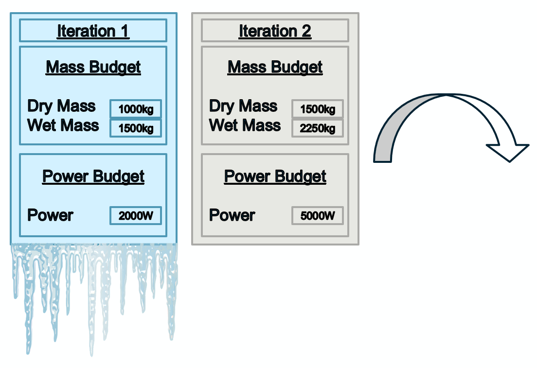
At the Internal Final Presentation (IFP) the final iteration is created and no more changes can be made in the model.
Study Models and Catalogues Models
In COMET there are two common types of models, Study Models and Catalogue Models.
A Study Model contains the elements required for a specific system for a specific mission. This is the primary model used during a CDF study and also the model that the entire team has access to. Each domain contributes to the Study Model and is responsible for making their own Element Definitions and Element Usages. The System team has the responsibility to maintain the overall model, budgets and iterations.
A Catalogue Model contains a collection of previously created Element Definitions that have been used in previous studies. This is the secondary model used during a CDF study and it is only used when more Element Definitions are required in the Study Model. Each domain (Power, Thermal, etc.) has their own Catalogue Model which can only be accessed by users from that domain. It is each domain expert’s responsability to maintain their domain’s Catalogue Model.
When a new Study Model is being built, it is always worth to double check within the relevant Catalogue Model if there are any Element Definitions that can be reused in the new study. Similarly, at the end of a study any newly created Element Definitions that are not present in the Catalogue Model can be reviewed to see if it is worth adding them to the Catalogue Model to be re-used in future studies.
