Cameo Systems Modeler adapter - Tutorial
Table of Contents
Introduction
In the tutorial section, you will see how to use the software performing basic tasks.
Getting Started
To get started 2 simple tasks are required to be accomplished.
Starting MagicDraw
Run your MagicDraw and open a SysML model.
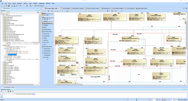
Figure 1:MagicDraw with a model open
Opening the adapter panels
Opening of the panels can be performed by pressing the button with the COMET icon in the tool bar.
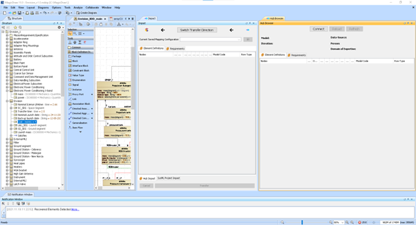
Figure 2:MagicDraw with the adapter panels showing
Connect to the hub by pressing the “Connect” button.
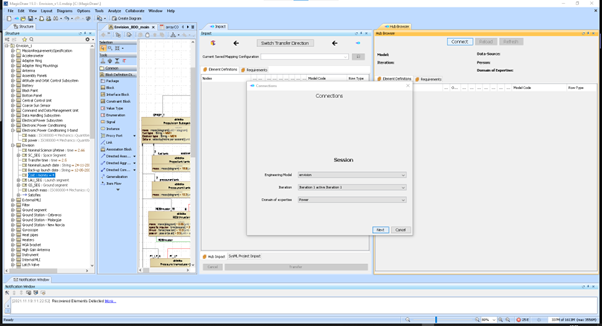
Figure 3:Connecting to a COMET® server and opening an Iteration.
Select the desired Engineering Model, Iteration and Domain of Expertise and press Next.
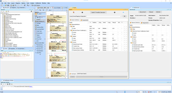
Figure 4:The main window with the ElementDefinition tree after opening an Iteration.
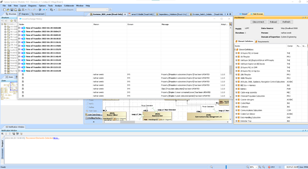
Figure 5:The local exchange history
Using the Software on a Typical Task
Mapping from a SysML model in MagicDraw to E-TM-10-25
- First, change the transfer direction so that the mapping source is the SysML model.
- Select one Element to be mapped with its children in one of the MagicDraw element trees.
- Right click on your selection and select “Map Selection”.
- Map one of the selected Block Element to one ElementDefinition or choose the automatic mapping defined by the mapping dialog.
- Map one of the selected Requirement Element to one RequirementsSpecification or choose the automatic mapping defined by the mapping dialog.
- Inspect the net change in the impact view and select the mapped elements to be transferred.
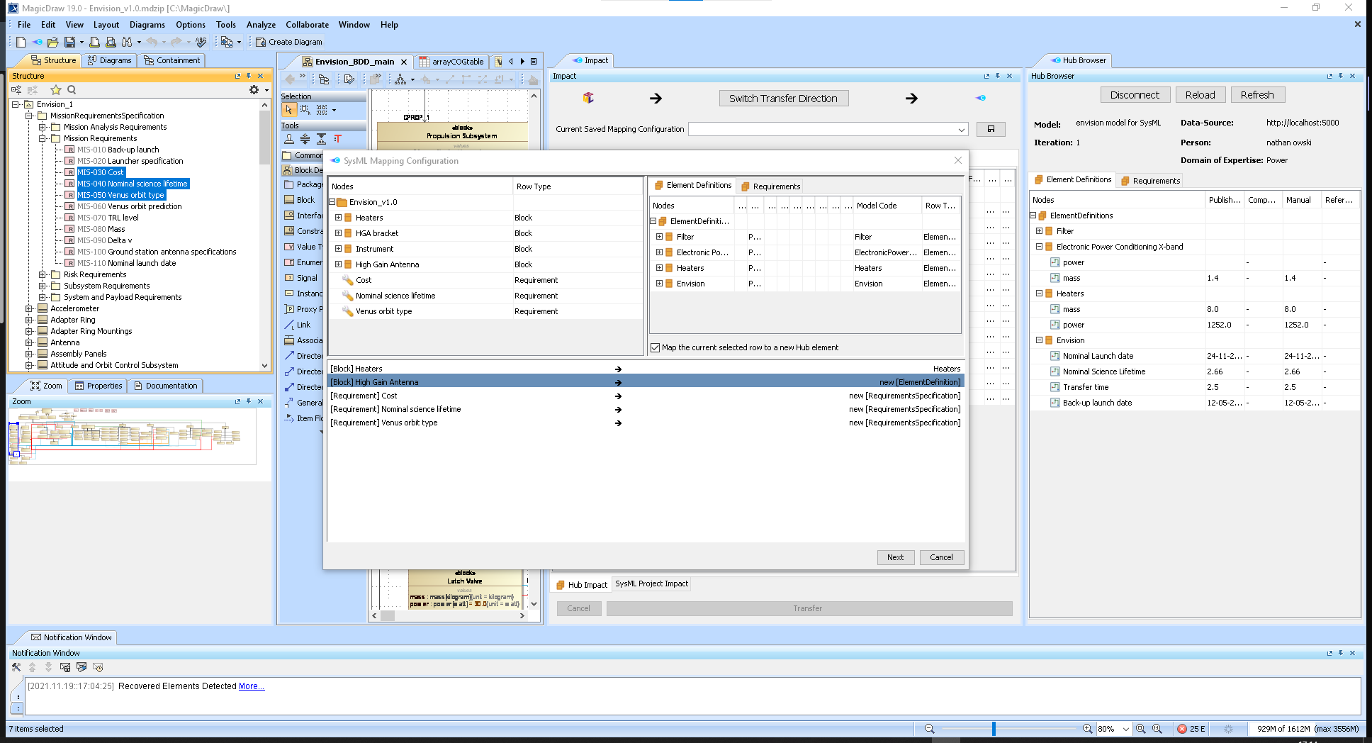
Figure 6:Mapping the selected elements to ElementDefinition and RequirementsSpecification.
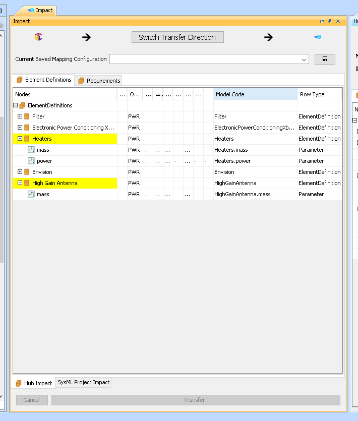
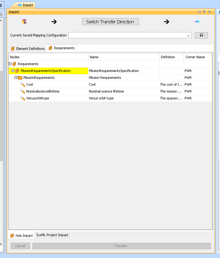
Figure 7:The value has been mapped and the relevant trees are highlighting the differences.
Mapping from a Comet model to SysML
- First, change the transfer direction so that the mapping source is the Comet model.
- Select one Element to be mapped with its children in the MagicDraw element browser.
- Right click on your selection and select “Map Selection”.
- Map one of the selected ElementDefinition to an existing Block element or choose the automatic mapping defined by the mapping dialog.
- Map one of the selected Requirement to one MagicDraw Requirement or choose the automatic mapping defined by the mapping dialog.
- Inspect the net change in the impact view and select the mapped elements to be transferred.

Figure 8:Mapping an Element Definition to SysML.
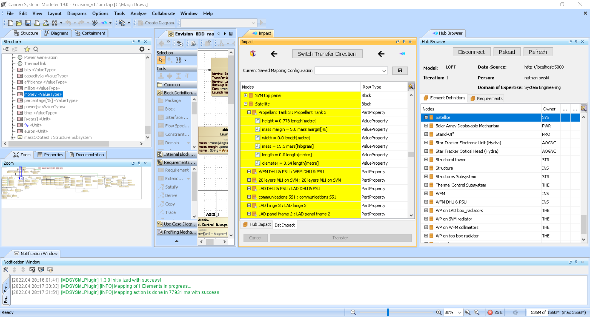
Figure 9:Impact view on the SysML model.
Transferring
When you have some mapping defined, you can select among the mapped element of what element you want to transfer. This can be achieved by manually select each element or by using the context menu like shown in the Figure 10. Please note that any relationship created during the mapping are only transferred if the elements one relationship connect are transferred at the same time. The same rule applies to interfaces when mapping to SysML.
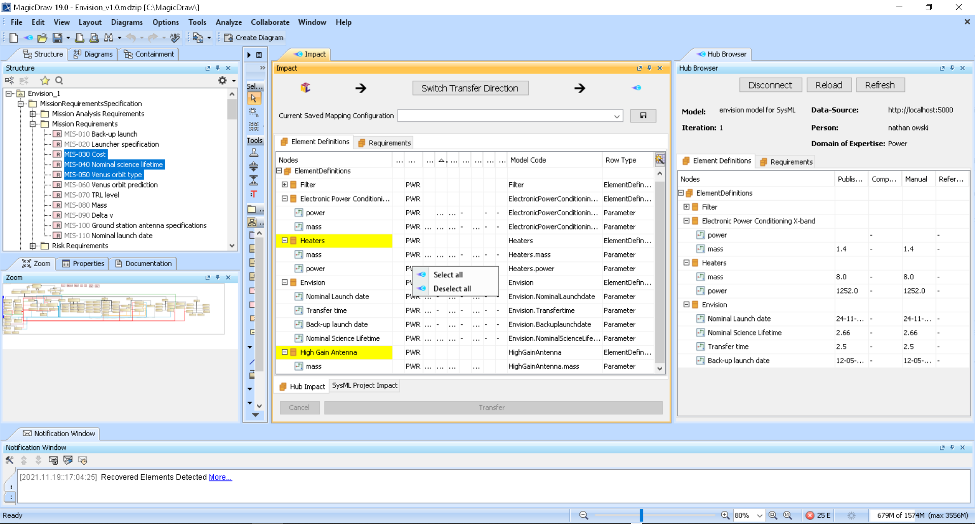
Figure 10:Impact view context menu 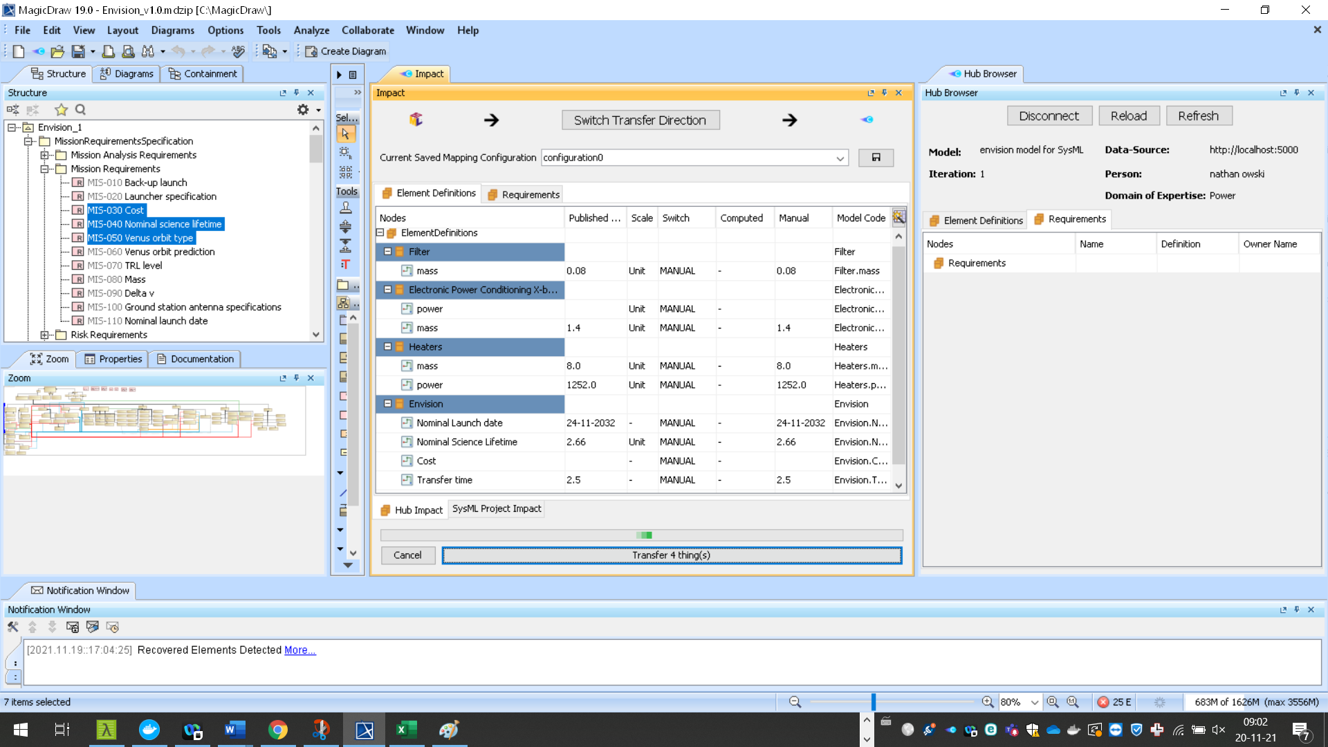
Figure 11:Transfer in progress of the selected elements.
The Figure 11 shows that the transfer is in progress. When it is done any loaded mapping configuration will be reloaded.