Preparing the Study Model structure
Table of Contents
- Renaming Mission and Spacecraft Element Definitions
- Examples of Study Model architectures
- Creating study specific Element Definitions
Once the Study Model has been created and the Active Domains and Participants required have been added, the model can be prepared for it’s CDF study. This setup of the model is specific to each CDF study and should always be coordinated with the Systems team.
This may include the following aspects (note that the below descriptions assume a model creation based on the template)
- Renaming the Mission and Spacecraft Element Definitions.
- Removing subsystem Element Definitions that are not needed.
- Introducing additional elements to compose the model architecture (such as orbiter and lander or payload module and service module).
- Create Element Definitions for known aspects of the model that are not equipment, such as propellant or the launch adapter.
- It is good practice to also already discuss Options and Finite States in the model with the Systems team in the preparation of the study, and subsequently:
- add Options to the model.
- add Finite States to the model.
- Introduce study specific Element Definitions not categorised as
Equipment. - Prepare report templates (and if applicable, link them to the model).
NOTE: It is recommended to only add additional architecture elements as well as Options and Finite States to the model during the initial CDF study sessions
Renaming Mission and Spacecraft Element Definitions
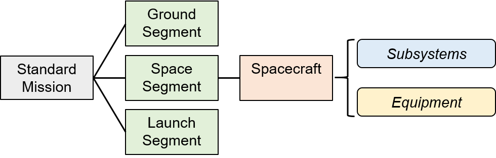
When creating a model from the template (see here), the model will include a preliminary architecture. The architecture from the template will be set up as follows, starting from the Mission Element Definition as the Top Element:
MissionGround SegmentLaunch SegmentSpace SegmentSpacecraftAOGNC Subsystem- ….
Thermal Control Subsystem
To change the name of the Mission as well as the Spacecraft Element Definitions according to the CDF study name and elements:
-
Find the
MissionElement Definition in the Element Definitions browser. -
Right-click and select
Edit. -
Edit the
Name(this will be displayed). TheShort Namecan also be edited if needed. -
Verify that the
MissionElement Definition has theIs Top Elementbox checked. -
Confirm with
OK. -
Double-check that the
MissionElement Definition is now highlighted as Top Element by bold font in the Element Definitions browser. -
Repeat steps 1-3 & 5 for the
SpacecraftElement Definition.
⚠️ WARNING: When changing the name of an Element Definition, make sure to also change the name of any Element Usages. This does not happen automatically. To check if an Element Usage exists for a given Element Definition right-click on the Element Definition and selecting
Highlight Element Usages.
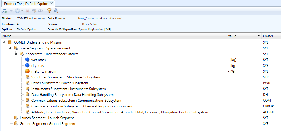
The resulting model archictecture can be visualised from the Product Tree browser - see advanced section.
NOTE: The example uses the standard mission architecture with a single spacecraft. Please see below for further examples for model architectures that are regularly used in CDF studies
Examples of Study Model architectures
Default Architecture: The default model architecture included in any model created from the template includes a single spacecraft. It provides the following features:
- Suitable for the standard CDF study covering the design of a single spacecraft.
- Suitable to cover less detailed payload modelling.
- Budgets can easily be established at spacecraft level.
- Subsystem Functional Representation can be used at spacecraft level.
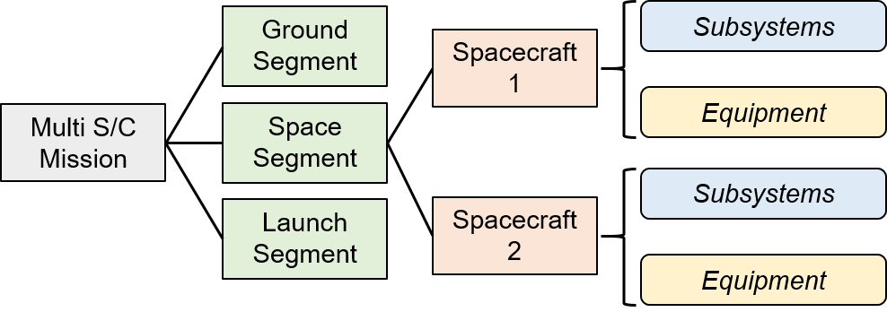
Multiple Spacecraft Architecture: Can be easily derived from the template by duplicating the original spacecraft Element Definition and renaming it accordingly before dragging the additional spacecraft Element Definitions into the space segment as a new Element Usage. It provides the following features:
- Fully independent modelling of multiple spacecraft (such as an orbiter+lander, two different satellites in formation flying, a small (< 5) number of satellites etc…).
- Budgets can easily be established for each individual spacecraft.
- Overall launch mass budget (in case of combined launch) can be derived.
- Subsystem Functional Representation requires Parameter Overrides when identical subsystems are used in different spacecraft.
- If desired this architecture can be used with Options to model entirely different spacecraft depending on the Option (by making the Element Usage of each spacecraft Option dependent).
- This approach is not recommended to model numerous identical spacecraft (see constellation).
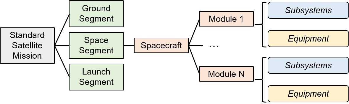
Detailed Modular Design Architecture: Can be derived from the template by introducing additional Element Definitions representing different modules and their Element Usages inside the main spacecraft Element Definition. These Element Definitions should typically be categorized as Elements and owned by SYE. This architecture provides the following features:
- A typical use case would be a satellite with a payload module and a service module. The architecture is then suitable for detailed platform and payload design including a high number of Element Usages inside the payload module with different ownerships (e.g. to model in detail the Mechanism, Thermal Control, Instrument, Power, etc distribution of a telescope payload).
- A similar architecture can also be used in case a model should be split according to subsystems that are different from the standard Domains of Expertise in COMET (e.g. a payload which is composed of a Module A, Module B and Module C where each of these modules needs to contain elements owned by
STR,MEC,TC,PWRetc…). - Budgets can easily be established for the individual modules and the overall spacecraft.
- In this architecture the subsystem Element Definitions could also be added inside the overall spacecraft for the initial step of the Functional Representation.
Constellation Architecture: When modelling a constellation of identical spacecraft (usually satellites) it is not desirable to individually model each spacecraft. A single spacecraft can be modelled in full detail and then be used in multiple Element Usages inside the Space Segment to model the different orbits in a constellation. This architecture provides the following features:
- Detailed modelling of 1 satellite of the constellation prevents the model from being overloaded by numerous individual but identical spacecraft.
- Easier tracking of changes inside single satellite (compared to individual but identical spacecraft).
- Budgets can easily be established for single satellite.
- Overall launch budget (in case of simultaneous launch) needs to be derived from individual budget.
- The orbit parameters can then be directly added inside the spacecraft Element Definition. Parameter Overrides can subsequently be used to model the different orbits of the different Element Usages of the satellite.
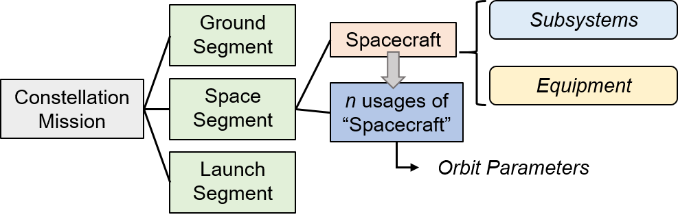
⚠️ WARNING: If the spacecraft in the constellation are not identical, this approach cannot be used since it is only possible to override parameters one level deep in an Element Usage. In this case, the Multiple Spacecraft Architecture defined above should be used instead.
Creating study specific Element Definitions
The majority of Element Definitions composing a typical Study Model will be the Subsystem Element Definitions used in the Functional Representation (see here and the Element Definitions describing an equipment derived from the Generic Equipment Element Definition or any other existing equipment from the domain Catalogue Model.
These typical Element Definitions are categorised accordingly as Subsystem and Equipment (see here for more details on the Categories used in COMET). Depending on the Study Model it can however be useful to also create additional Element Definitions not based on the Subsystem or Generic Equipment Element Definitions and using a different Category to delineate their specific status in the study model. A typical example for this would be Element Definitions describing the fuel and oxidizer in a spacecraft using chemical propulsion. These Element Definitions will contain a restricted set of Parameter Values (i.e. only a mass parameter) and can be individually linked to the report templates to produce a correct mass budget providing a spacecraft dry mass and wet mass (see here).
NOTE: Creation of these additional Element Definitions should be agreed with the Systems team and domain experts involved (i.e. the Chemical Propulsion expert when creating the fuel/oxidizer Element Definitions)
To create a blank Element Definition:
-
From the Model tab open the Element Definitions browser.
-
From the
 icon select
 Create an Element Definition. -
Enter
Short NameandName. - If applicable: change
Ownerto the applicable Domain of Expertise.NOTE: Inform the domain experts of this step to raise awareness of their responsibility to main this Parameter Value.
-
In the same dialog window switch to the Categories tab.
-
Select the appropriate Category from the list. For fuel/oxidizer
ConsumableorPropellantis recommended. -
Confirm with
Ok. -
The empty Element Definition is now available in the Element Definitions browser and parameters can be added from the Reference Data Library as described here.