Step 3D adapter - Reference manual
Table of Contents
- Introduction
- Help Method
- Screen Definitions and Operations
- Commands and Operations
- Connecting to CDP4 Hub
- Refresh information in the Adapter
- User Settings Dialog Box
- Load a local STEP file
- Specification of Mapping Configuration
- File to Hub: define a mapping
- File to Hub: Transfer the mappings
- Retrieving a STEP file from the hub.
- Visualize a STEP file on the Hub
- The Step File Comparison Functionality
- Publications
Introduction
The developed GUI relies on some components used in some other adapters (provided by the DEHP Common .NET package). These components offer all classical user interaction process like:
- Clicking on buttons
- Selecting files by selectors
- Checking check boxes
- Scrolling list
- Frame with tabs
- Right click on entries to open context menus
and permit to the users to understand quickly how things can be done.
Help Method
No online help is available for the moment because all operations are done manually in the GUI. Note that some helps are available in the GUI by passing the mouse pointer at interesting location of the interface and waiting for a second, letting appear a “tooltip” at the location of the pointer to guide the user about the purpose of the underlying object, helping the user during the execution of his task.
Screen Definitions and Operations
The STEP-AP242 main window, shows practically all the information the user requires, therefore a minimum screen resolution of 800 pixels by 600 pixels. It is possible to resize the different inner panels to accommodate the view. It does not contain any window top menu, but some operations are available through context menu or by selecting tree items in the relevant panels.
Commands and Operations
Connecting to CDP4 Hub
In the Hub Data Source frame of the main window, you have to click on Connect button and fill requested information in the dialog box that will appear.
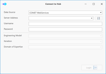
Figure 2 : Connection to CDP4 Hub with STEP-AP242 adapter
First, you will have to specify:
- Data Source
- Server address
- Username
- Password
and click on Login button. Once the connection is established, you will have to fill the second part of the dialog box by specifying:
- Engineering Model
- Iteration
- Domain of Expertise
and click on Continue button. You are now connected to the Hub Data Source.
Refresh information in the Adapter
To retrieve the last information in the Hub (for example, modifications in the Hub due to other people working on the same engineering model at the same time), you have to click on the Refresh button:
in the right Hub Data Source frame of the main window. The information from the Hub is updated in the Model, Publications, and File Store tabs.
User Settings Dialog Box
On the righthand bottom corner of the application the button opens the User Settings Dialog box.
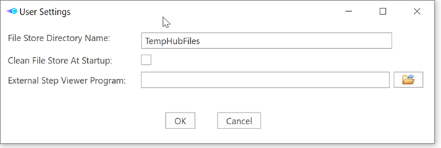
Figure 3 : User settings dialog box for STEP-AP242 adapter
The available user settings are:
- File Store Directory Name: This is the name of the subdirectory, located in the application directory that will be used to store the files retrieved from the hub.
- Clean File Store At Start-up: If selected, the content of the file store directory will be deleted when the application starts.
- External Step Viewer Program: if this field is left blank, the application will use the system defined step viewer application. If you add the path or browse to another step viewer application, it will be used in all the commands that open a step file.
Pressing OK will save the modified user preference.
Load a local STEP file
Click on Load STEP-AP242 file of the STEP-AP242 frame of the application. A new dialog box appears and you have to specify the local STEP file to load.
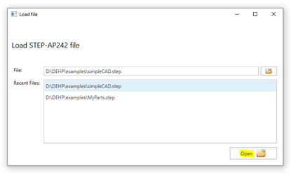
Figure 4: Loading a local STEP file with STEP-AP242 adapter
You can select the file by browsing the drives and subdirectories on your computer or select a file among “Recent Files” box. Then click on Open button. The file is loaded and you will then be able to visualize the general information in the Header section and the HRL tree which complete the STEP-AP242 frame of the application. If when loading the file there is an active connection to a Hub Data Source, then the Mapping Configuration Manager dialog is displayed select the associated mappings to be used in the current STEP file (see next section).
Specification of Mapping Configuration
In order to avoid the manual mapping of objects very time an input file is selected, the mapping can be saved on the hub under a configuration name. This supports the user by restarting from existing mapping information and he has just to specify the change/add when he performs new mappings. As this configuration is saved in the Hub, other users of the STEP AP242 adapter can access immediately as this is available. The following image you can see the Mapping Configuration Manager of STEP-AP242 files:
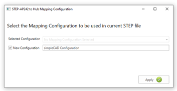
Figure 5 : Defining the mapping configuration with STEP-AP242 adapter
- Selected Configuration: list of mapping configurations already available in the Hub Data Source.
- New Configuration: when checked, you must to specify the name for new one.
By clicking on Apply button the selected or a new configuration is be applied to the current HLR replacing previous mapping configurations. In case of closing the dialog without applying a configuration, everything remains unchanged.
File to Hub: define a mapping
Once a local STEP file is loaded, you can start to map HLR parts to Element Definition and Element Usages by performing a right-click on the part and selecting “Map [part description]” item from the context menu.
Mapping data structure
The STEP part data is mapped to an Element Definition or Element Usage, on a step geometry compound parameter. If this parameter does not exist in the Element Definition it will be added at the transfer time. Note: the step geometry parameter is automatically created by the adapter on the Reference Data Library of the selected Engineering Model. The step geometry is composed by the following parameters:
- name: the name of the STEP part.
- id: StepId of the Product_Definition of the STEP part.
- rep_type: STEP class name used to define the geometry for the Product_Definition of the STEP part.
- assembly_label: label identifying the instance in the tree composition (only when a part is used inside as a child of another part).
- assembly_id: StepId of the Next_Assembly_Usage_Ocurrence which defines the composition between two parts (only when a part is used inside as a child of another part).
- source: Unique Id of the FileRevision which holds the STEP file stored in the hub.
All this information will be associated to the Element Definition or Element Usages and will permit to link the right geometry contained in the STEP file that will be stored on the Domain File Store. For your information, the resulting step geometry compound parameter is seen like this
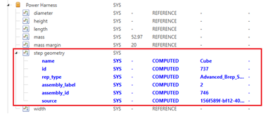
Figure 6 : The “step geometry” compound parameter
in the GUI. Here the selected entity (“Cube”) is mapped on Power Harness Element Definition.
Mapping configuration rules for File to hub
Once a mapping is initiated by a right-click on an entity of the HLR of the STEP file, the dialog box in Figure 7 appears.
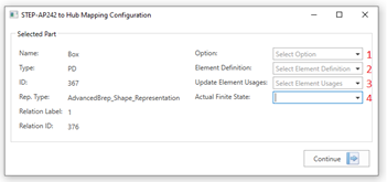
Figure 7 : The mapping configuration dialog box of STEP-AP242 adapter
in which you have to enter optionally 4 fields.
- The Option serves to two purposes. When selected, only Element Usages include in the selected option are available. Also, is the selected the ElementDefinition contains a step geometry parameter which is option dependent, then selected Option will be used to set the values. A warning message will appear in case the step geometry parameter is “Option Dependent” and no Option was selected. To make a step geometry parameter “Option Dependent”, you can use COMET-CE.
- Select one Element Definition. If no Element Definition is specified, a new Element Definition named as the Part name will be created.
- Select one or several Element Usages. When selecting Element Usages of one Element Definition, all the overridden step geometry parameters will be updated. If one selected Element Usage has its step geometry parameter that is not set as “Overridden”, the selected Element Definition will be impacted by the mapping. The “Overridden” state of a parameter can be for example set in COMET-CE.
- Select the Actual Finite State to consider when the step geometry parameter is “State Dependent”. To set a step geometry parameter as “State Dependent”, you can proceed with COMET-CE. For more details, please consult COMET-CE documentation.
Notes:
- A mapping operation can be done several times before transfer of information to the Hub.
- Once a mapping is defined, the impacted Element Definition and Element Usages will be highlighted in green in the Impact frame at the center of the main window of the STEP-AP242 Adapter:
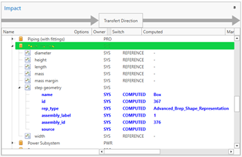
Figure 8 : Impact view of STEP-AP242 adapter (things to transfer are highlighted in green)
File to Hub: Transfer the mappings
Once all the requested mappings are set/added for the selected STEP file, the user can decide to transfer them to the Hub. But before doing the transfer, the user can decide to not transfer some of the mappings. By default, the mappings are highlighted in green in the Impact view. If you click on any of them, it will change to yellow and will not be transferred. You can click on yellow ones to make them green again so that they are finally transferred. There is context menu that will allow to select/unselect all of them in one operation. For example, in the next picture, as the power harness is yellow, it will not be transferred.
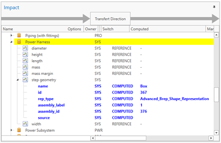
Figure 9 : Impact view of STEP-AP242 adapter (things to not transfer are highlighted in yellow)
Once all the mappings to transfer have been decided, the user can launch the transfer. To proceed, he has to click on Transfer button in the main window. Then, the user is invited to introduce “Justification”:
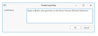
Figure 10 : Specification of log entry to associate to a transfer to Hub
in order to create a log entry in the Hub in order to help in the monitoring of reasons for changes.
Retrieving a STEP file from the hub.
This functionality just permits to retrieve a STEP file from the Hub. From the Hub Data Source frame, there are 2 possibilities:
- From File Store tab, select the file and click on “Download As…”
OR
- From the Model tab, retrieve directly the STEP file containing the geometrical description of an Element on the Hub starting from the Element itself (by a right click)
Mapping a STEP file from the hub to a local STEP file is not possible in this Adapter because modifying an existing STEP file is not an obvious task.
Visualize a STEP file on the Hub
From the File Store tab in the Hub Data Source frame of the application, you can use the Open button to visualize directly the selected STEP file by a CAD application that is installed on your computer. Note: Do not forget to associate .step (and .stp) file extensions to this application installed on your computer (Example: FreeCAD). The selected CAD application has to support STEP format. You can also set an application you want to use in the User Settings.
The Step File Comparison Functionality
It is possible to do a High Level comparison between the loaded step file and the one selected from the hub.
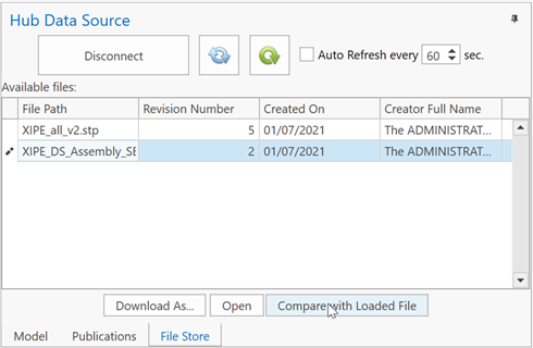
Figure 11 : Calling the STEP files comparison functionality Once you have loaded a file (using Load STEP-AP442 file), you can select a file in the Hub Data Source File Store. After that you can trigger the comparison between the two files using the Compare with Loaded File button. It will then display a dialog box similar to this one:
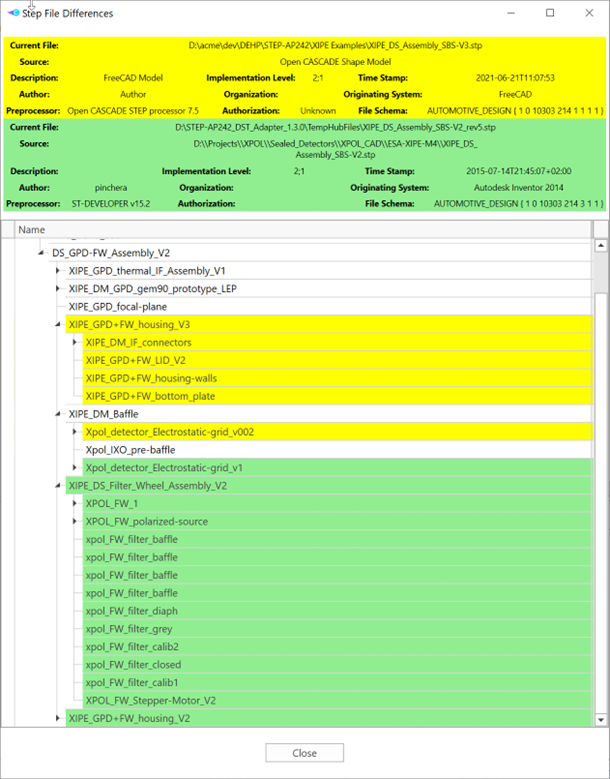
Figure 12 : STEP files comparison result
The Loaded File content is in yellow. The HUB file content is in green. High Level Representation that is similar in both files is displayed in black. Please note that the HLR representation in only based on names. If you have two files that contains similar data with only the root of the structure bearing a different name, they will be considered as being completely different. When the files are considered being different, you will see two coloured trees.
Publications
With the STEP-AP242 adapter, you can visualize current publications by selecting Publications tab in Hub Data Source frame on the right part of the main window.