STEP TAS adapter - Tutorial
Table of Contents
Introduction
The STEP-TAS DST Adapter can be used for typical tasks. For example, it can used for :
- Transferring a local STEP-TAS file to the Hub with mapping information
- Generate input information for an ESATAN computation using information stored on the Hub (i.e. “mean consumed power” property)
- Once the ESATAN computation is performed locally and CVS files containing temperature results are generated, upload these results on the hub in linked Element Definitions / Element Usages.
These 3 typical tasks will be specifically detailed below in “Using the Software on a Typical Task”
Getting Started
The GUI of the STEP-TAS Adapter is launched by running the [INSTALLATION_DIRECTORY]\DEHPSTEPTAS.exe file. After the splash screen mentioning the version of the software, the following main window appears
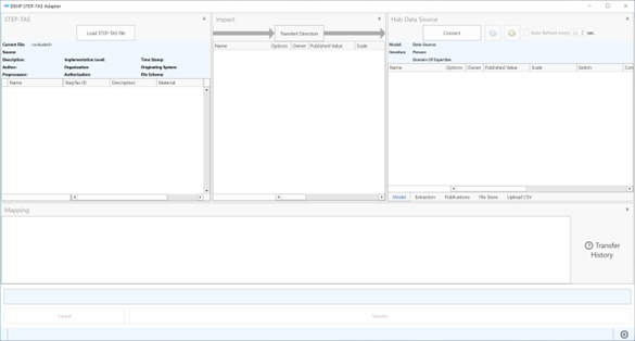
Figure 14: The main window of STEP-TAS adapter
Then, before guiding the user through the 3 typical tasks mentioned in the introduction, we need to explain how to get connected to the ECSS-E-TM-10-25 Data Source in the application. On the right Hub Data Source frame of the STEP-TAS adapter, you have to click on Connect and then, the following dialog box appears:
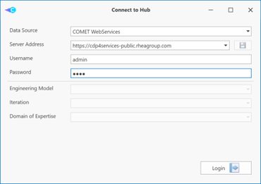
Figure 15: Connect to hub data source
Then, you will have to specify (example connecting to demo server at RHEA)
- Data Source: COMET WebServices
- Server address:
https://cdp4services-public.rheagroup.com - Username: admin
- Password : pass
and click on Login button. Then, you will be invited to enter the Engineering Model, the Iteration and the Domain of Expertise after a refresh of the dialog box
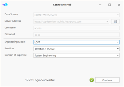
Figure 16: Selection of the Engineering Model, Iteration and Domain of Expertise
and then click on Continue. You are now connected to the first iteration of the model on the Hub as a System Engineer. The user is now able to start to work with the software and perform the 3 typical tasks mentioned in the previous section. Note: The LOFT Engineering model is maybe not fully adapted to illustrate the typical task but it has the great advantage that it already exists on the public demo server at RHEA.
Using the Software on a Typical Task
Transferring a local STEP-TAS file to the CDP4 hub
Load local STEP file
First of all, you have to load an existing STEP-TAS file in the DST Adapter. To proceed, click on Load STEP-TAS file in the “STEP-TAS” left frame of the application. Then a new dialog box appears:
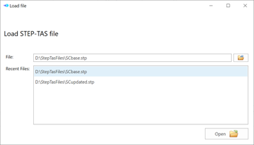
Figure 17: Open a local STEP-TAS file
in which you have to specify the local STEP-TAS file to load (here select SCbase.step in EXAMPLES directory). You can select the file by browsing the drive and subdirectories on your computer or select a file among Recent Files box if it was previously opened). Then click on Open and the following dialog box appears:
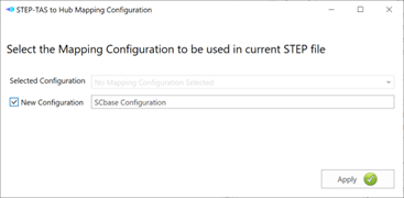
Figure 18: Select a mapping configuration
This selection permits to attribute an existing mapping information set (or create a new one in the present case) for the entities in selected STEP-TAS file. These entities are related to the HLR of the file. The HLR can be viewed in the left frame of the application. After successively expanding SC, SC_Body, SA_DEPL, SA_DEPL_NY and SA_DEPL_NY, we obtain:
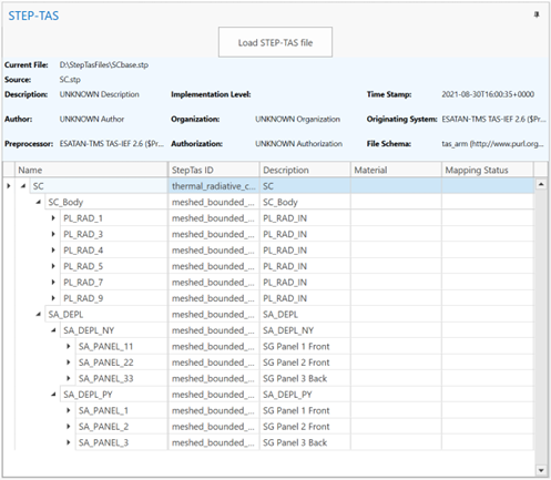
Figure 19: Partial HLR of SCbase.stp file
In the previous frame, you can observe that the “Mapping Status” column is empty because it was the first time that we deal with SCbase.stp file (we started from a new configuration).
Define a mapping
To perform a mapping between a CAD entity (a feature or part) and an Element Definition and/or several Element Usage on the Hub, you have to perform a right click on one entry in the HLR of the local STEP-TAS file. In the typical task, we will first perform a mapping of PL_RAD_1 (right click Map PL_RAD_1)
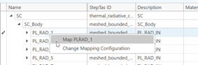
Figure 20: Initiate a mapping on PL_RAD_1
Then a new dialog box appears
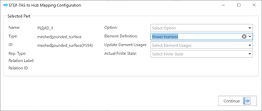
Figure 21: Define the mapping for PL_RAD_1
In which you have to specify on which Element Definition (here “Power Harness” from RHEA demo model) and click on Continue. You can then observe two things in the adapter:
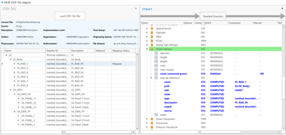
Figure 22: Mapping status in HLR
- The “Mapping Status” related to “PL_RAD_1” feature is now assigned to “Mapped” in HLR.
- The impact of the mapping has introduced an additional compound parameter (step tas reference) to the Element Definition (here Power Harness) on which we have performed the mapping. Simply note that “source” field is empty because the STEP-TAS file is not yet transferred to the Hub. Note that when you perform a mapping, the Options and/or Finite States can only be supported if step tas reference is defined as “Option Dependent” and/or “Finite State” are defined for it.
This mapping operation can be repeated several times in order to perform other mappings if needed. For the purpose of the typical task, we will perform an additional mapping between “SC” in HLR of the local STEP-TAS file and the “Satellite” Element Definition on the hub data source.
Transfer to the Hub
Once the two mappings are done, they have to be transferred to the Hub. For this, you need to click on Transfer button on the lower part of STEP-TAS adapter application and the following dialog box appears
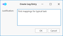
Figure 23: Create a log entry
in which you can optionally write a justification for the transfer (for follow-up reasons). This information will be stored on the Hub. The mapping is then “committed” and we can observe
- The “Mapping Status” related to “PL_RAD_1” and “SC” in HLR is now assigned to “Transferred”.
- The “source” field in step tas reference compound parameter is now assigned to an identifier. This identifier will permit to retrieve the associated step file that is now stored on the Hub.
Generate input information for an ESATAN computation In order to generate useful input for an ESATAN computation, we will assume that a “mean consumed power” parameter was already attached to “Power Harness” Element Definition and a value is set for this parameter (a published one or a value specified by “value switch”). If this parameter does not exist yet, you can add and define a value for it using COMET-CE. Then do not forget to push on Refresh button in the STEP-TAS adapter
before continuing.
Then, open the Extraction tab in hub Data source Frame and select the “mean consumer power” in Extract From combo-list. If the defined mean consumer power is State Dependent on the hub, you have to select the requested state in Finite State.
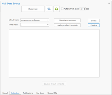
Figure 24: The “Extraction” tab to generate input for ESATAN
Since a file “mean consumed power.template” exists in the Templates directory (specified in User preferences), you can directly push on Extract or Preview button
- Extract button: A file steptas.ext will be generated in ExtractionOutput directory (defined in User Preferences) with the value of consumed power distributed at nodes.
- Preview button: The generation is done in a preview window.
The generated lines of code can then be integrated in the ESATAN model and the computation can be performed. Once the computation is done and a CSV files containing some temperature results is generated by ESATAN, you can go to the next step.
Upload temperature results to the HUB
To proceed, open the Upload CSV tab and Browse the temperatureResults.csv file in EXAMPLES directory and click on Analyze
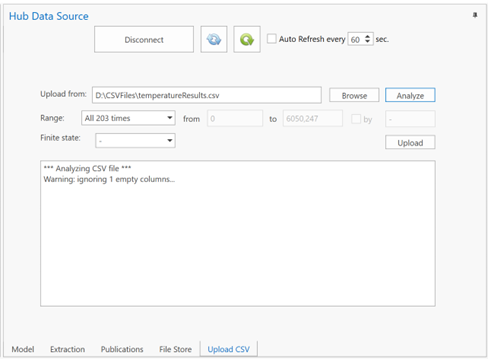
Figure 25: The “Upload CSV” tab after analyze of the selected CSV file
For this simple task, we will use the default Range (All 203 timesteps of the file) and we will Upload directly the results on the hub by clicking on Upload. In the selected CSV file, we have nodes that are only referenced by “Satellite” Element Definition (that is associated to SC in the STEP-TAS). This is then logical than only temperature results are uploaded inside “Satellite” on the hub.
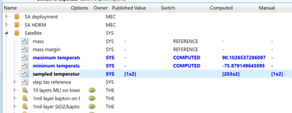
Figure 26: Generated temperature parameter on the hub after a “CSV Upload” (in COMET-CE)
This last stage closes the section “Using the software on a typical task”.