Astos adapter - Tutorial
Table of Contents
- Introduction
- Introduction
- Getting Started
- Creating an E-TM-10-25 Eclipse Analysis Scenario
- Importing Parameter values
- Running a Simulation
- Exporting Simulation results
- Transfer Log
- Adapter connection
Introduction
In the tutorial section we show how to use the ASTOS wizard to create a Scenario with inputs and outputs mapped to E-TM-10-25 Parameters. We also show steps to add further input and output mappings and what is required to set up the Adapter connection after ASTOS loads a Scenario.
For this tutorial, a special server must be used to 8 TUTORIAL
Introduction
In the tutorial section we show how to use the ASTOS wizard to create a Scenario with inputs and outputs mapped to E-TM-10-25 Parameters. We also show steps to add further input and output mappings and what is required to set up the Adapter connection after ASTOS loads a Scenario.
Getting Started
When a new ASTOS version is started for the first time, there is no scenario loaded and the actions that can be performed are limited. A new scenario must be created first (Figure 1).
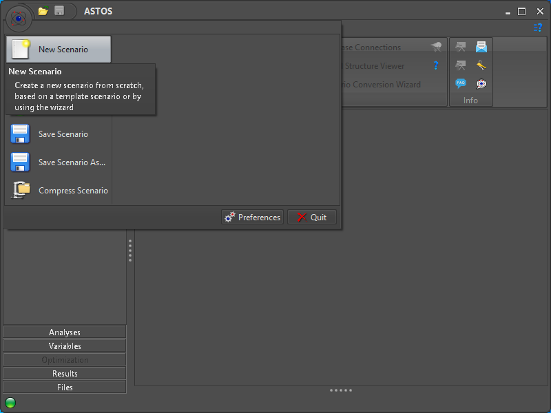 Figure 1: Initial start of new ASTOS version
A new ASTOS Scenario for certain Use Cases can be created with the help of the built-in Wizard. Using this option can be selected in the “New Scenario” dialog (Figure 2).
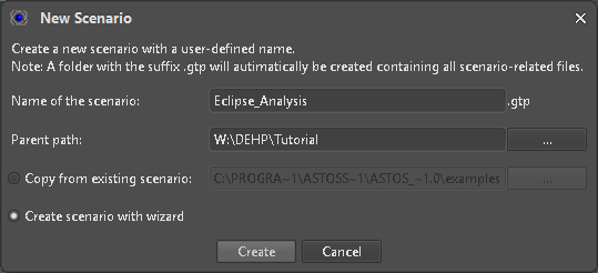 Figure 2: New Scenario Dialog
Creating an E-TM-10-25 Eclipse Analysis Scenario
For DEHP new kinds of Scenario setups were added to the ASTOS Wizard to cover the requested Test Cases and to allow initial mapping of Parameter (Figure 3).
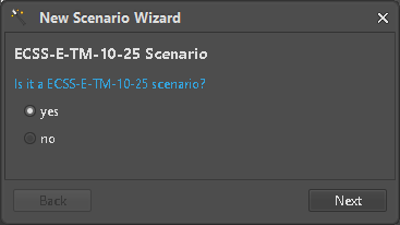 Figure 3: Select scenario type
Select Scenario and Application
The following Scenario Wizards are considered to be ready to use:
- Launcher design
- Coverage analysis
- Eclipse analysis
- Operational lifetime analysis For this tutorial we will use the “Eclipse analysis” Wizard (Figure 4).
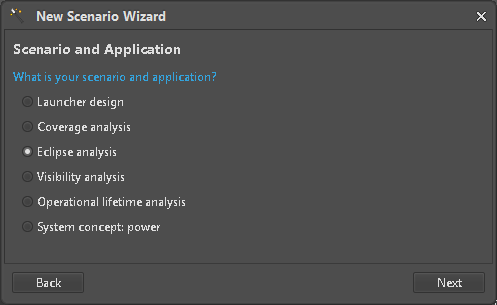 Figure 4: Wizard selection
After an initial Scenario description is shown (Figure 5), the next step is to connect to a E-TM-10-25 data source to map Parameters later on.
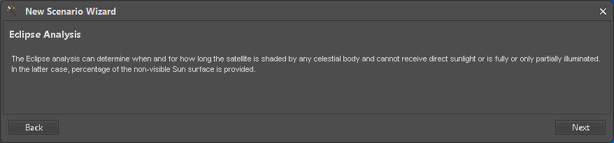 Figure 5: Scenario description
Connection Setup
A valid target URL with matching user credentials must be supplied (Figure 6).
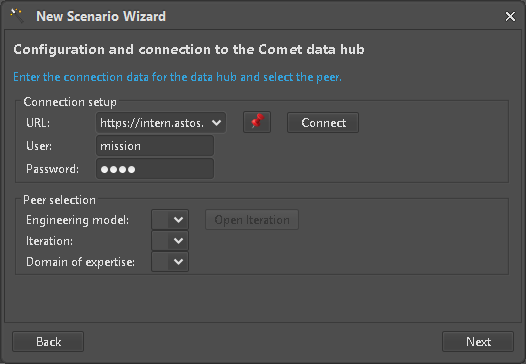 Figure 6: Connection setup
The correct EngineeringModel on the server in its current Iteration side must be selected (Figure 7) and opened (Figure 8) before continuing with the next step.
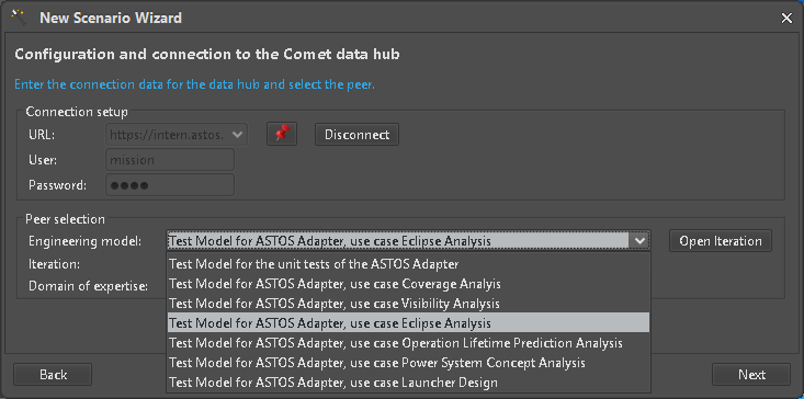 Figure 7: Selection of EngineeringModel
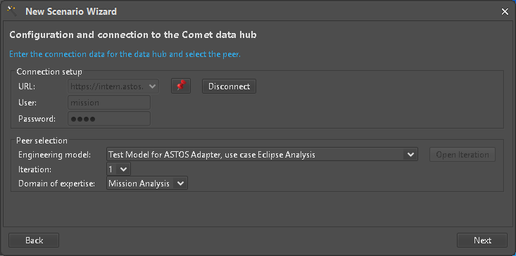 Figure 8: Open Engineering Model Iteration for Domain of Expertise
Input mappings
Until we reach the settings for Keplerian parameters, we accept the default values by just clicking the “Next” button. The Fields where Variables can be used and mapped to E-TM-10-25 Parameters are marked with a Comet icon (Figure 9) which are clickable to start the selection process (Figure 10). Only Parameters with a compatible Unit can be selected to. Mapped input elements are represented by an ASTOS Variable (blue box) but respective values are not yet pulled from the Hub (Figure 11).
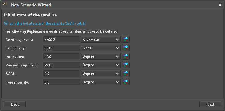 Figure 9: Keplerian settings
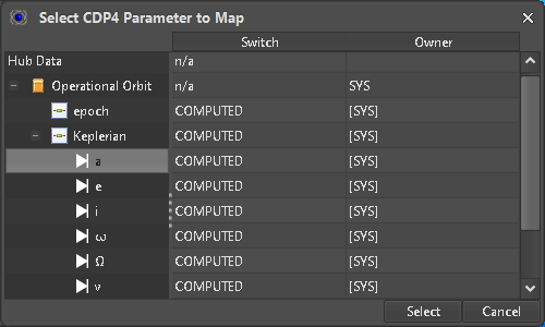 Figure 10: Parameter selection
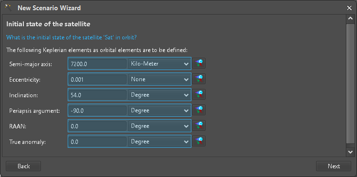 Figure 11: Fully mapped Keplerian input
Continue to create the Scenario and close the Wizard (Figure 12). A new Scenario with matching Analysis and Report is now completed (Figure 13).
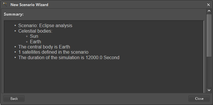 Figure 12: Scenario creation complete
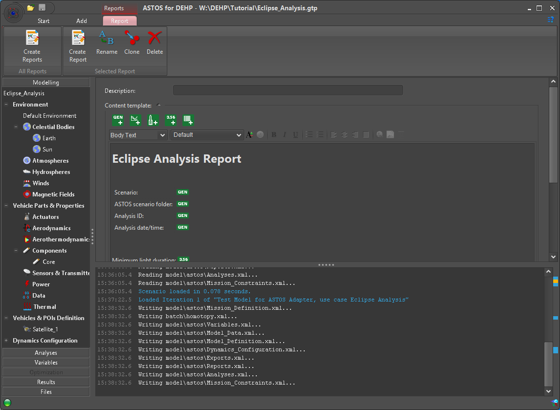 Figure 13: Scenario for Eclipse Analysis created
Additional input mappings
Further input mappings that are not covered by the Wizard or were skipped during Scenario creation can be added in places where ASTOS allows to use a Variable. As an example we add the “Mission start date” as an additional input mapping. Since the date is expressed as “Modified Julian Date” in the Test Cases, the respective representation must be selected in ASTOS as well. A new Variable for the “Date” can then be created by right-clicking the respective input field (Figure 14).
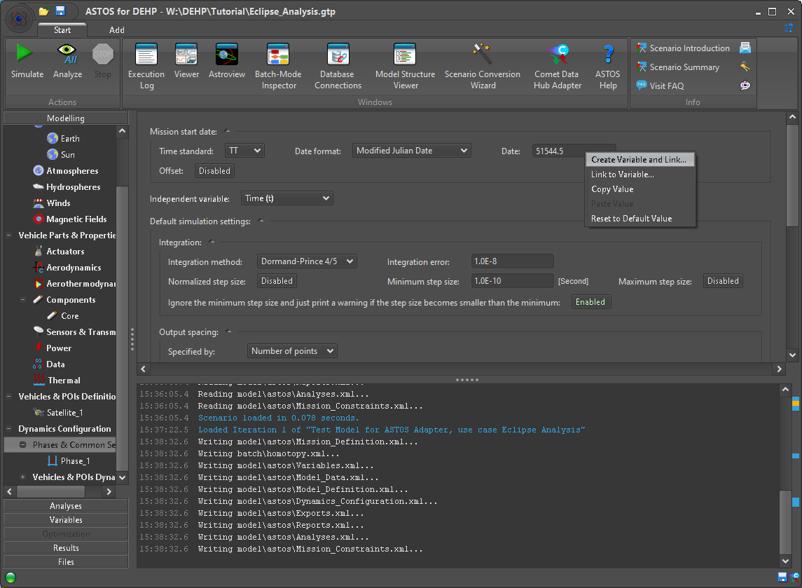 Figure 14: Create Variable for MJD format Date value
To create a Variable which can be mapped to a Hub Parameter the type must be set to “Comet Data Hub” variable (Figure 15). Since the target type in ASTOS is a raw Floating Point value no Unit filtering is done when selecting a Parameter from the Hub (Figure 16). All additional Variables of this type can be found next to the ones already created during Scenario creation (Figure 17).
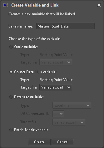 Figure 15: Variable type selection
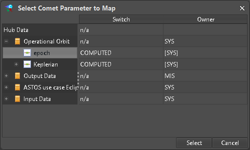 Figure 16: Selection of MJD target value
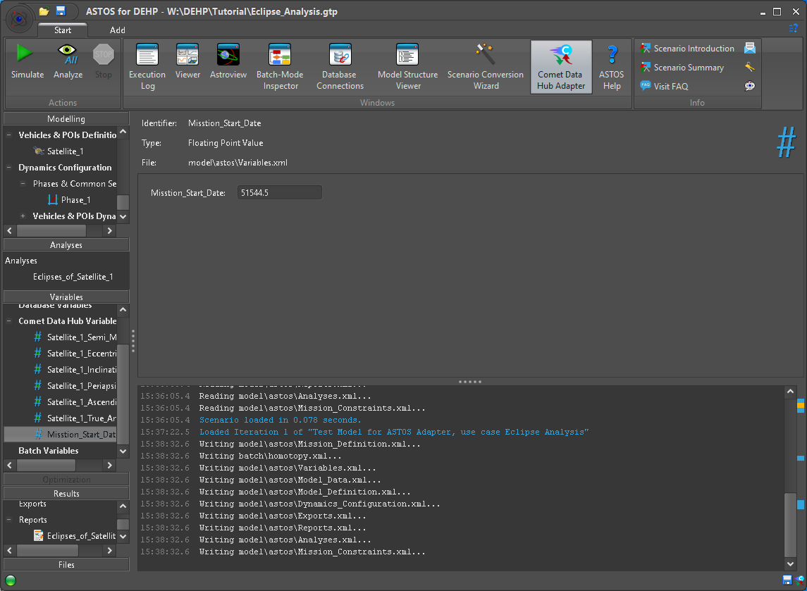 Figure 17: Comet Data Hub Variables
Importing Parameter values
A click on the Ribbon entry for the “Comet Data Hub Adapter” (Figure 17) shows a window with the current connection state and allows further interaction related to data manipulation and transfer. Here information on mapped local and remote data is shown and we can review and select specific values to import (Figure 18). When doing so the local value is set accordingly, conversion in case of Unit differences is applied automatically.
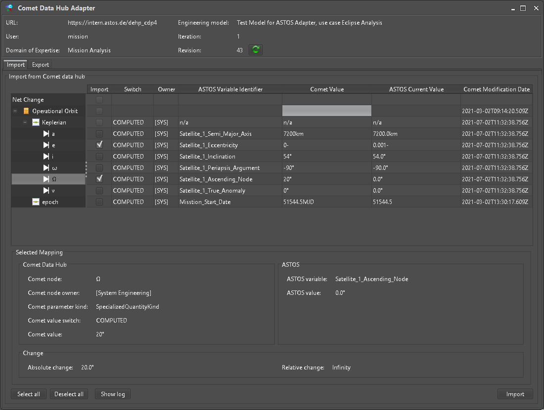 Figure 18: Import view of Comet adapter
Running a Simulation
So far no output data was created. This can now be run by pressing the “Simulate” button on the main ASTOS window (Figure 14). A new “Execution Log” window is shown to report Simulation steps, progress or errors (). By default, the associated “Eclipse Analysis” is configured to also run after each Simulation.
Exporting Simulation results
To push new data to the Hub, a different kind of Parameter mapping is required. Initially the “Export” tab of the “Comet Data Hub Adapter” is empty. New entries are created via the “Add” button (Figure 19).
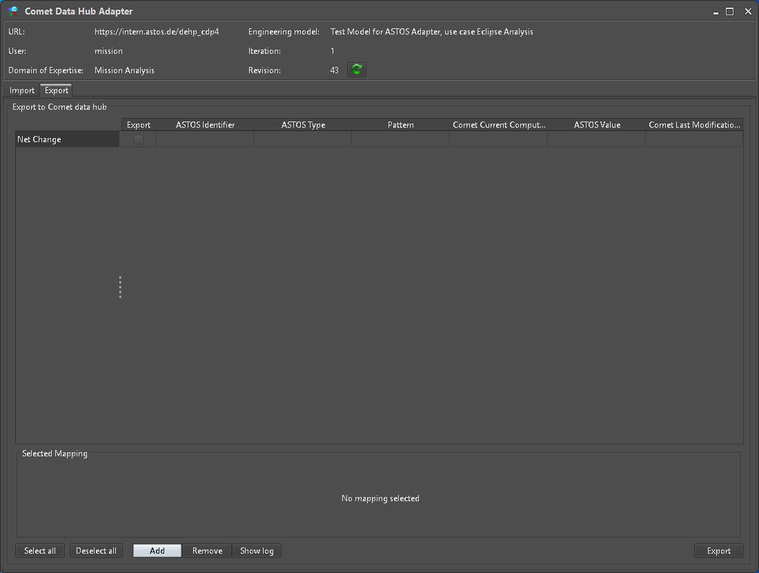 Figure 19: Initial Export view
In case a scalar ParameterType is selected (Figure 20), a ASTOS Item of matching Unit can be mapped (Figure 21). Only Parameters belonging to the current DomainOfExpertise are allowed to be mapped as output.
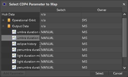 Figure 20: Scalar ParameterType output value selection
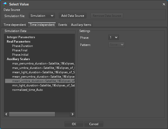 Figure 21: Scalar output source selection
For a CompoundType each entry must be assigned to a valid scalar ASTOS Item. Similarly when adding a SampledFunctionParameterType (Figure 22) for each row a matching ASTOS Item must be configured via the “Link” dialog (Figure 23). Here it is also possible to reduce the amount of data to be pushed to the hub by selecting a “Minimum sampling interval”.
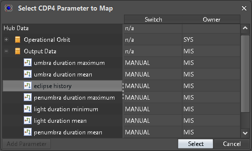 Figure 22: SampledFunctionParameterType output value selected
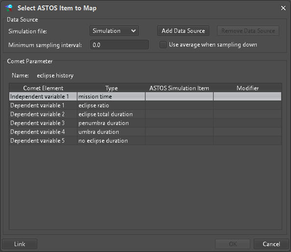 Figure 23: Empty value mapping
The Unit of each entry must be compatible with the selected target type to link (Figure 24). It is also allowed to link elements which can be converted by simple time integration or derivation.
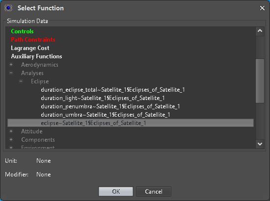 Figure 24: Element link dialog
If all elements are successfully linked the output mapping can be created (Figure 25).
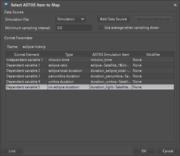 Figure 25: Completed value mapping
The local value to be exported to a scalar ParameterType can be edited directly on the “Export” panel of the “Comet Data Hub Adapter”. For a SampledFunctionParameterType only dimensions are shown (Figure 26). Further information and data manipulation can be done from the “Change Details” dialog (Figure 27) accessible by the “Details” button.
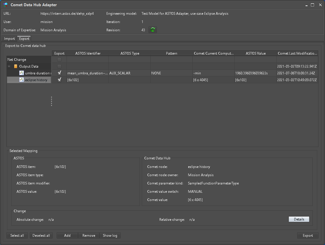 Figure 26: Configured exports view
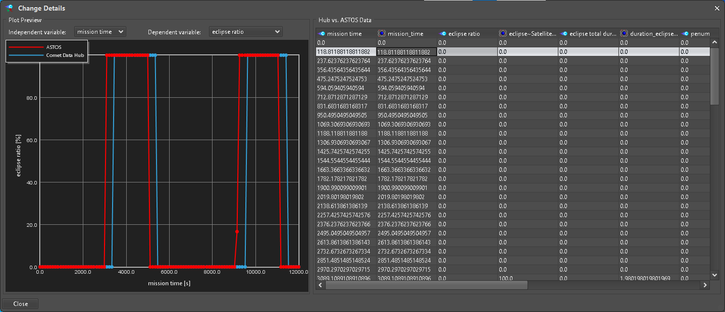 Figure 27: Change Details dialog
It can be selected for which mapping data is to be transferred when pressing the “Export” button. If during a transfer a newer revision is detected on the Hub, the export is aborted and an error message is displayed. This is done so the user can verify if the new data still applies based on checking the configured input mappings and changes in output data that are to be pushed to the Hub.
Transfer Log
A log of transfer is written to the ASTOS Scenario folder to keep track of data exchanged with the Hub (Figure 28). A graphical representation can be shown by pressing the “Show log” button on the “Comet Data Hub Adapter” window.
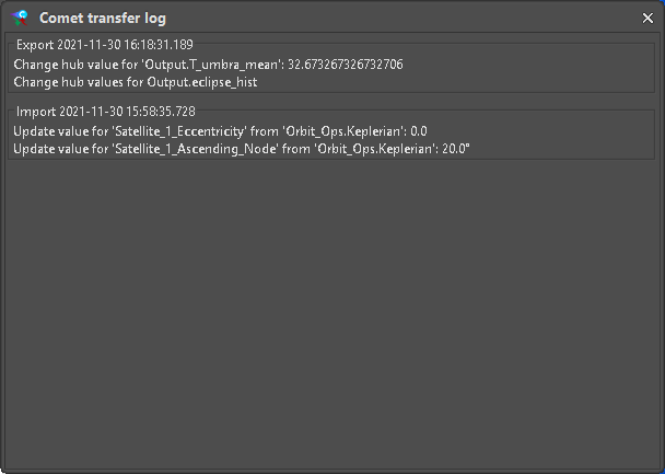 Figure 28: Transfer log window
Adapter connection
While the initial connection to the Hub is set up by the Wizard, this has to be done each time the ASTOS Scenario is loaded. Since credentials are not part of the Scenario they must be supplied each time when opening a new connection. Only the URL is retained and mapped to user-configured aliases if applicable. The respective input fields for “User” and “Password” are located on the panel for “Comet Data Hub Variables” (Figure 29).
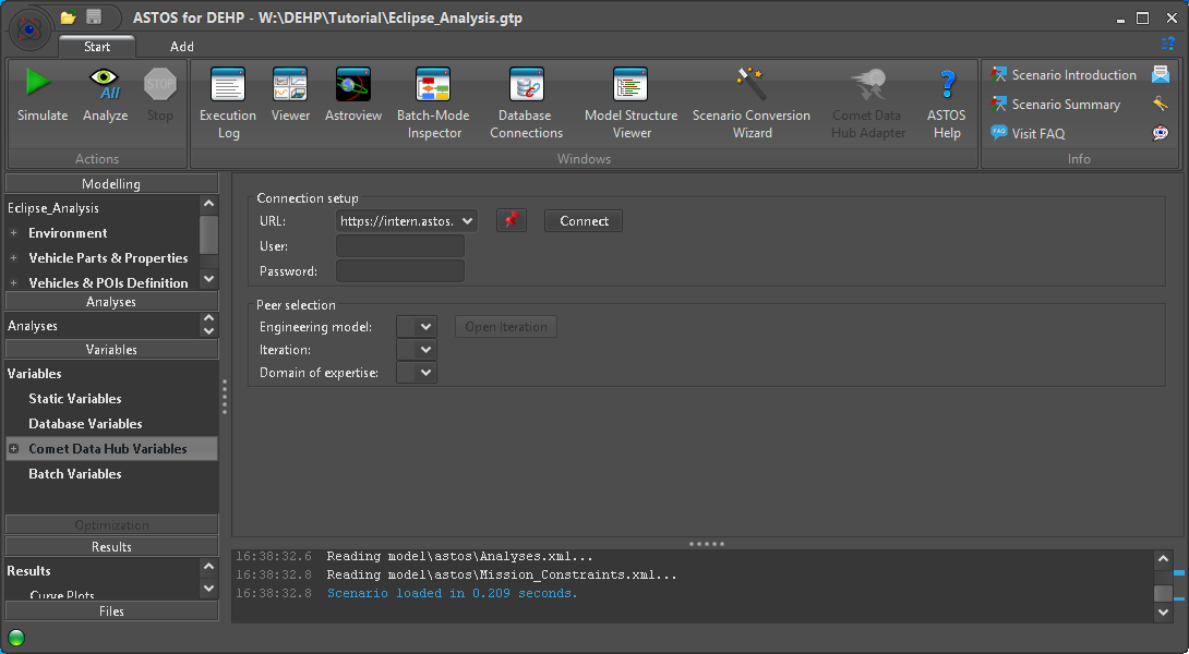 Figure 29: Adapter connection settings
Settings for “Peer selection” are saved to the Scenario and are restored (if possible) after a connection is established, so the user can just open the preselected Iteration.