Generic Example
The following example can be used to familiarise oneself with COMET. The steps recreate the typical usage of the tool which experts are expected to fulfill during a CDF study.
Logging into COMET
-
Open the Citrix service: link to Citrix.
⚠️ Make sure the Citrix Workspace client is installed through the software center and ensure to be connected to the ESA VPN
- Login to Citrix using ESAAD personnal credentials.
User name: ESA AD UsernamePassword: Windows Password If login fails, please reach out to the study’s Assistant Systems Engineer (ASE).
-
Navigate through the available applications to find and open COMET.
If the COMET application does not launch, click here
* If an `.ica` file is downloaded, refer to the section `Automatically Open ICA Files` applicable to your browser [here](https://support.citrix.com/article/CTX804493/users-prompted-to-download-run-open-ica-file-instead-of-launching-connection) * If a Citrix Workspace window pops up asking to `Add Account` this can simply be closed. Ticking the `Do not show this window...` box will prevent this from happening every time. * If a windows firewall pop-up appears, it can beclosed and ignored. After closing the firewall window COMET wil launch automatically.If you experience issues with the resolution of the COMET window, click here
In some cases, COMET does not launch with correct display resolution settings. The text on the window might appear very small or the mouse pointer might have an offset with where it is pointing. In these cases, the following steps should resolve the issue. 1. Close COMET and navigate to the Citrix *Advanced Settings* by right-clicking the Citrix icon in the hidden icons of your Taskbar. 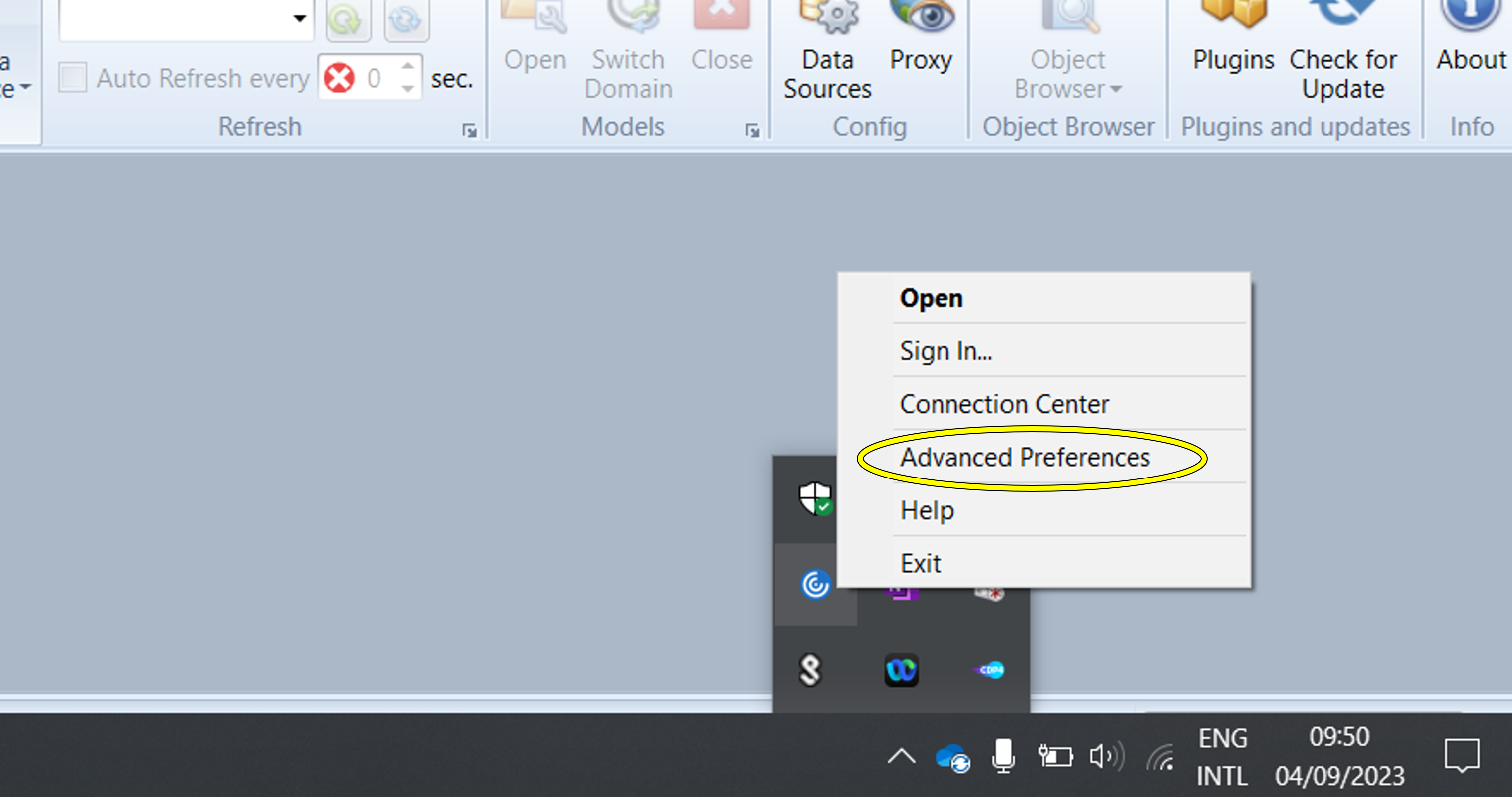 2. Set the **High DPI** setting to "Let the operating system scale the resolution". 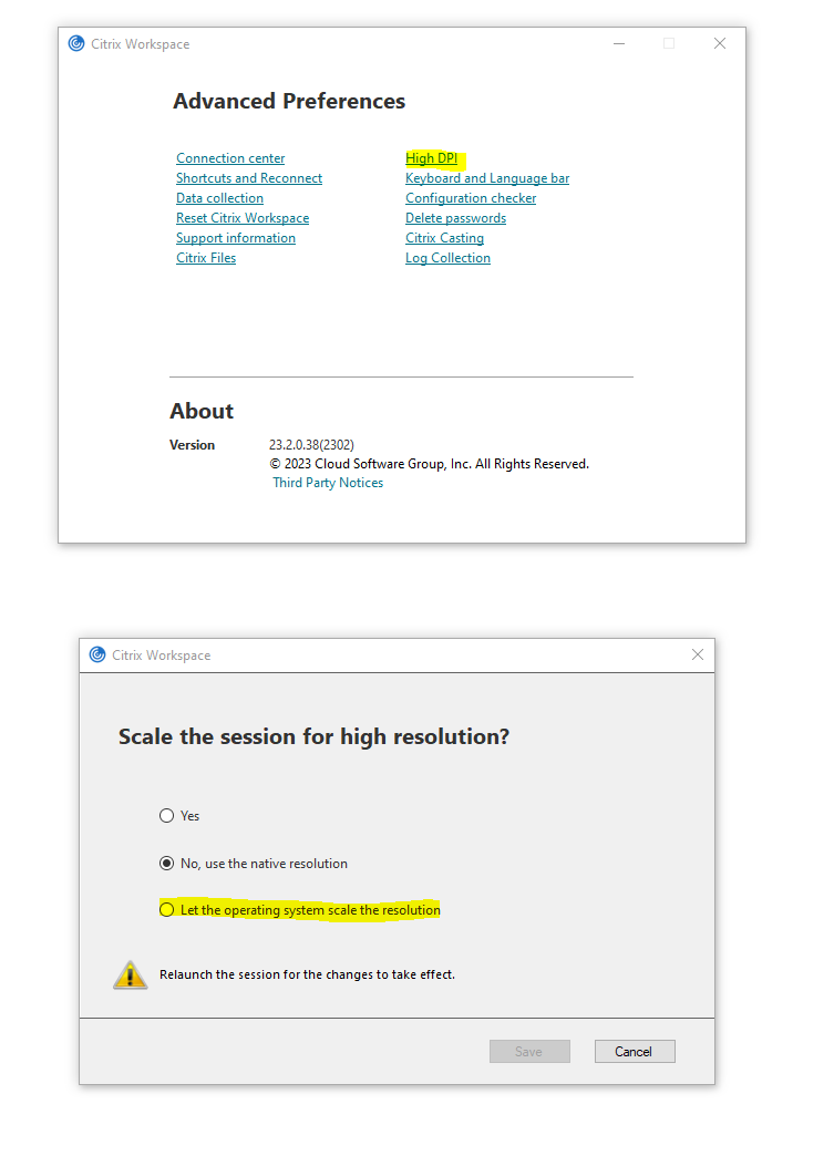 3. Save your preferences. 4. Restart the COMET Application. If these steps did not resolve the scaling issues you are facing, contact the Assistant Systems Engineer for your study. -
Once COMET is open, click on the
Connecticon .
. -
Select the pre-programed
Source Address:COMET-PROD.NOTE: If there is no pre-programmed Source Address, enter the following URL manually in the field:
https://comet-prod.esa-ad.esa.int -
Enter COMET credentials (⚠️COMET and Citrix credentials are different). COMET credentials are provided by Assistant Systems Engineer (ASE).
-
Click
Connect and Open Model. -
Upon a successful login, the Iteration Selection dialog shows a list of the available models.
Opening Models
In COMET projects are called Models, and they are built up of Element Definitions aggregated into systems. Oftentimes, from one Study Model to the next, Element Definitions are similar or even identical (e.g sun sensors, star trackers, solar cells, mechanisms, thrusters, tanks…). To optimize the modelling experience, it is possible to make use of Catalogue Models, that contain components used in previous CDF studies, and re-use them.
-
Select the Study Model indicated by the Assistant Systems Engineer and either click
Openor double click to open it.
⚠️ WARNING: Upon successful opening only a small text at the bottom left of the window indicating:
Info | Loading model took ...will appear -
It is good pratice to check the
Auto Refreshtick box and enter 60 seconds. This feature will ensure that every 60 seconds the COMET Application will make a request to server and update the application with any changes.
-
In the Home tab, click on the
Openbutton to open the Iteration Selection dialog again and also open the Catalogue Model corresponding to your domain.
NOTE: Study Models and Catalogue Models are only visible to users who have been given access to them. If the required model does not appear, reach out to the study’s Assistant Systems Engineer
</details>
-
Navigate to the Model tab and click on
Element Definitions. You will be able to choose between the models you have opened. Do this twice to open the Element Definition browser for both the Study Model and the Catalogue Model.
-
Move the browsers so they are side by side.
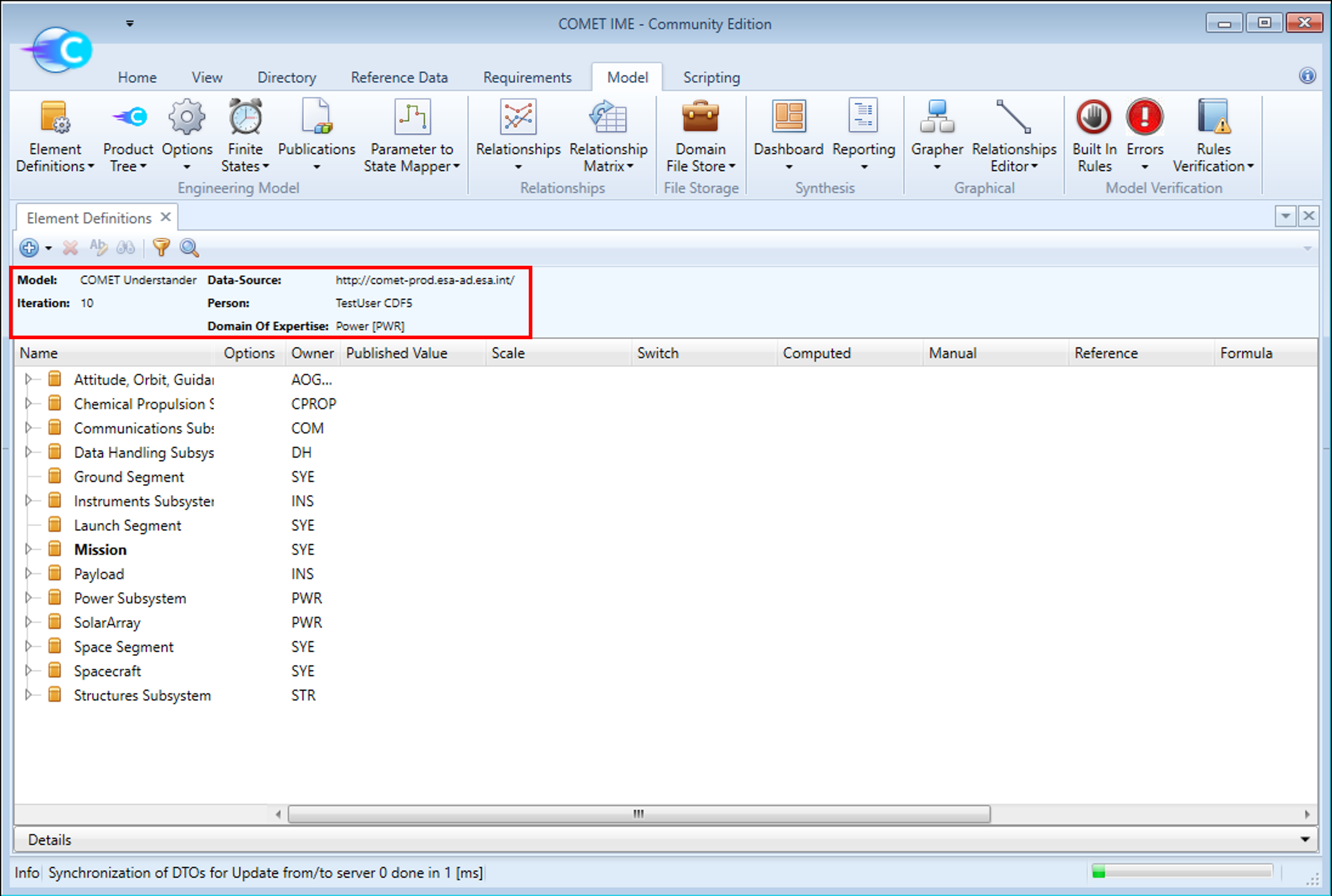
In COMET, Element Definitions are used to model veriouis aspects of the system. They can describe anything from the highest level (e.g. the Mission) to the smallest component (e.g. an Engine Valve for Propulsion System). Element Definitions contain information on the thing they are trying to represent (more on this later) and relationships between them are created to form a complex system (more on this later). The Element Definition browser provides an overview of all the Element Definitions in the model. It can be considered a box of lego bricks with individual Element Definitions of individual things, which can be used together to form a complex system.
The top of the the Element Definitions browser contains some information about the Study Model or Catalogue Model and the user such as model name, domain of expertise, etc.
Modelling Equipment
With this setup, it is now possible to start modelling. The next steps will explain how to model a new equipment in the Study Model using the Catalogue. The Catalogue Model contains a set of pre-defined Element Definitions that were created by experts of previous CDF studies. They are generally quite comprehensive and, in most cases, will contain an Element Definition describing the typical equipment used on Spacecraft. Normally, when creating a new equipment, the Catalogue Model should be searched to see if there already is an Element Definition describing the equipment in question. In this example, it is assumed this was done and no matching equipment was found. Therefore, the Generic Equipment will be used to model a new equipment.
-
Copy the
Generic Equipmentfrom the Catalogue Model to the Study Model by holdingCTRL+SHIFT, clicking on theGeneric Equipmentin the Catalogue Model and drag-and-dropping it into the Study Model:
Holding
CTRL+SHIFTensures that the parameter values are kept the same as they are in the catalogue. If, on the other hand, it is desirable to set all the parameter values the default “-“,SHIFT+ drag and drop is sufficient.SHIFT+ Drag and Drop: The values are set to the default “-“.CTRL+SHIFT+ Drag and Drop: The values are set to values as defined in the catalogue. -
Right-click on the newly created
Generic Equipmentin the Study Model and click onEdit. This will open a new dialog from which you can define what the Element Definition is modelling. For the following steps, pretend you are adding an equipment which belongs to your subsystem (e.g. a reaction wheel, a propellant tank, a battery, etc.). -
The
Short Nameis a unique identifier for an Element Definition. It is used to ensure that the Element Definitions can be re-used in different studies without change. Change theShort Namefollowing these rules:- The first character must be a Latin letter.
- Remaining characters must be alphanumeric characters or underscores.
- Cannot contain spaces.
- It should be clear and unambiguous.
-
The
Nameof an Element Definition is what is seen in the Element Definitions browser. It should clearly and understandably describe the Element Definition it belongs to. Change theName, leave the rest untouched and clickOK.
-
Expand the Element Definition you have just modified to reveal the parameters inside it. Parameters define the characteristics of an equipment and are represented by the icon
 . All equipment should have the 24 standard parameters you see in the
 Generic Equipment(note that they are grouped in folders to ease navigation). -
Dedicate some time to familiarise yourself with these parameters.
-
You can now close the Element Definition browser of the Catalogue Model.
Parameters
Next, we will add a new parameter to the Element Definition you just created. Additional parameters (beyond the standard 24) can be added to Equipment in the Study Model if additional information must be captured on COMET. A large number of additional, pre-defined parameters are tabulated in the Reference Data Library (RDL).
-
Open the RDL browser by navigating to the Reference Data tab and click on
Parameter Types: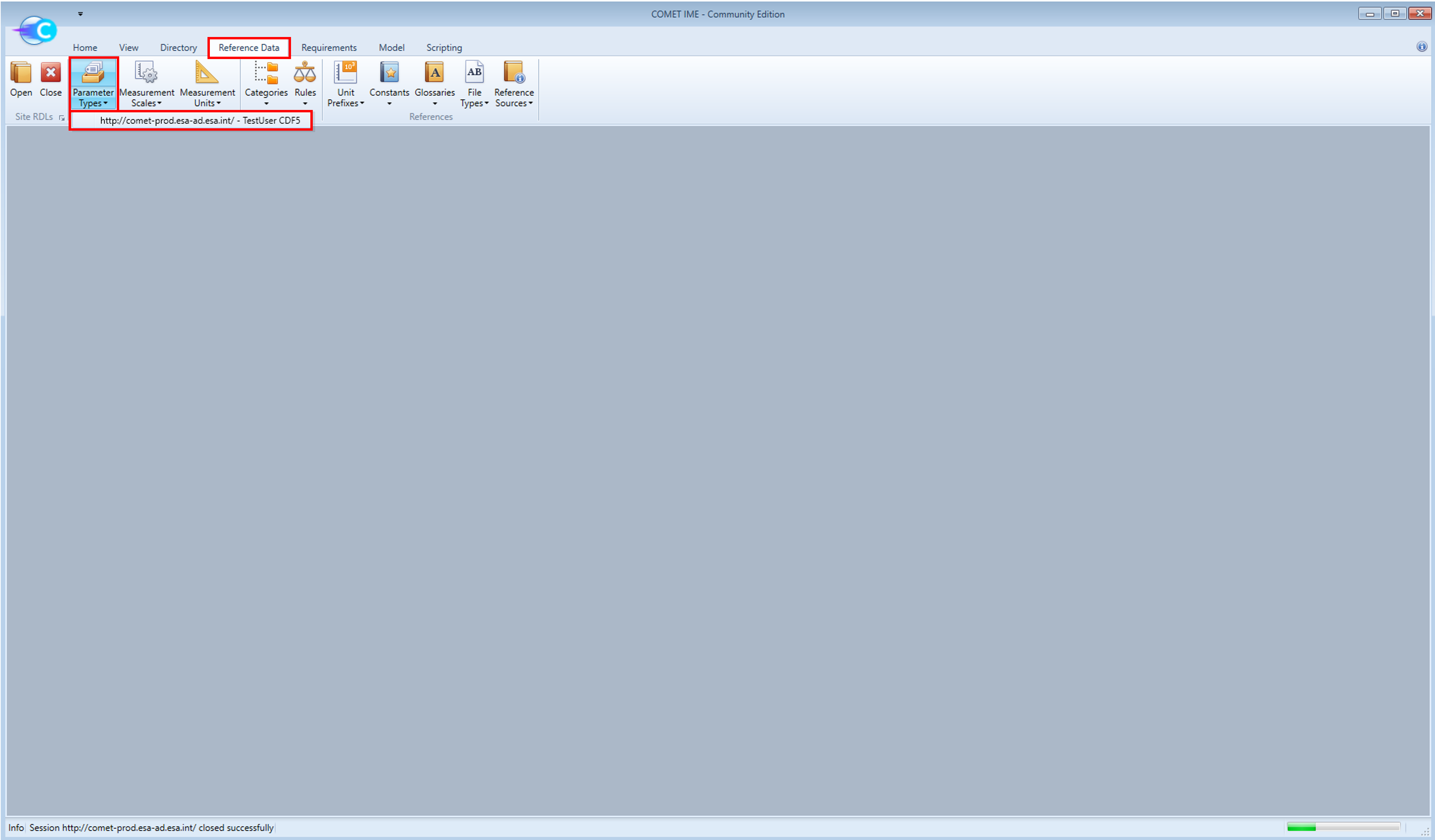
-
Place the RDL browser and the Element Definitions browser side-by-side. This allows to easily move parameters between the two.
-
Find a parameter relevant to the Equipment you are modelling (e.g.
torqueif you are modelling Reaction Wheels) in the RDL browser and simply drag and drop it on the newly created equipment:
NOTE: You can drop the parameter directly on the Element Definition name or in one of the folders inside the Element Definition if you prefer.
-
Now that the Equipment has been modelled and all necessary parameters have been added, it is possible to give Parameter Values to each parameter. To assign a Parameter Value to a parameter, navigate to that parameter in the Element Definitions browser and fill in the value in the
Manualcolumn. The purpose of theComputedandReferencecolumns are explained here. Fill in the values for the parametersmass,maturity margin,power while onand the newly created parameter which you added from the Reference Data Library.
NOTE: Ensure you input the value in the correct scale as defined in the
Scalecolumn on each parameter.NOTE: During the CDF study, you will be expected to populate all Parameter Values for the equipment you create.
-
You can now close the Reference Data Library browser.
Product Tree
- Now, open the
Product Treeby navigating to the Model tab and clicking onProduct Tree. You will see theProduct Treeof the Catalogue Model and theProduct Treeof the Study Model - click on theProduct Treeof the Study Model.NOTE: If more than one Option is defined in the Study Model, you will be prompted to choose which options you wish to view (the concept of Options will be tackled later). Study Models for new CDF studies will typically not have Options defined at first but this tutorial model does for completness. For now, just click on either one of the two Options.
- Place the Product Tree view next to the Element Definition browser.
While the Element Definition browser displays all Element Definitions on the same level, the Product Tree view provides a tree-like breakdown of the model, based on the relationships between Element Definitions. The standard tree structure for a CDF study is:
- Mission
- Ground Segment
- Launch Segment
- Space Segment
- Spacecraft
- Subsystem 1
- Subsystem 2
- …
- Equipment 1
- Equipment 2
- …
- Spacecraft
Notice that, for each “entry” in the Product Tree view, an Element Definition is defined in the Element Definitions browser. The top element in the Product Tree view, the Mission, is highlighted in bold in the Element Definitions browser.
The mission is modelled by nesting Element Definitons into one another, starting from the Mission and going down to equipment level. By dragging and dropping Element Definitions from the Element Definitions browser onto the Product Tree view, they are added to the system (and thus also to the Product Tree view) and Element Usages are created. Element Usages are instances of Element Definitons that are being used in the system. Multiple Element Usages can be created from a single Element Definition. In COMET, Element Definitons are represented with the icon ![]() and Element Usages with the icon
and Element Usages with the icon ![]() .
.
Creating Element Usages
-
Create an Element Usages of your newly created Equipment in the
SpacecraftElement Definition. Bear in mind that the parametern_itemwill define how many times the equipment will be accounted for in the system:
⚠️ WARNING: Do NOT drag equipment into the subsystem Element Definitions. These are functional representation of each subsystem as described here. Always, only drag equipment into the spacecraft/platform (the name of this Element Definition will be indicated by the Assistant Systems Engineer)
⚠️ WARNING: Do NOT nest equipment. Even if one equipment is a sub-component of another equipment, all equipment Element Usages must be one level deep under the spacecraft/platform (the name of this Element Definition will be indicated by the Assistant Systems Engineer)
NOTE: Only Element Usages, which make up the model, will be counted in the budgets (mass budget, power budget, etc). If an equipment is defined (as an Element Definition in the Element Definitions browser) but not used (as an Element Usage in the Product Tree view) it is not a part of the system
⚠️ WARNING: When changing the name of an Element Definition in the Element Definitions browser, make sure to also change the name of any Element Usage in the Product Tree view.
Finite States
The systems team will use your inputs on COMET to generate the Mass budget, the Power budget, the Equipment list, etc. The Power budget in COMET requires the use of Finite States which are used to model the system modes of the spacecraft. The tutorial model only has two system modes: the Safe Mode and the Operational Mode. The varying power consumption of an equipment during each mode is defined with the power duty cycle parameter. This parameter describes the percentage of time the equipment is active during a given state. It can take the following values:
| Value | Meaning |
|---|---|
| 0 ≤ power duty cycle ≤ 1 | A percentage of the time the equipment is consuming power during the given state. A value of 0 means the equipment is on Standby and does NOT mean the power consumed during the state is 0 W |
| -1 | The equipment is off for the entire duration of the state and will consume 0 W of power |
NOTE: The calculation of the
mean consumed power, which is dependant on thepower duty cycle, follows the (simplified) equation:
P_mean = [ P_on * DC + P_Stby * (1 - DC) ] * [ 1 + MM ]
where: P_mean is themean consumed power, P_on is thepower while on, DC is thepower duty cycle, P_Stby is thepower in standbyand MM is the equipmentmaturity margin.
To model the varying power consumption of your equipment during the two system modes:
-
Right-click on the
power duty cycleparameter of your equipment from the Element Definition browser. -
Click
Edit. -
Find the
State Dependencedrop down list. -
Select the
system modesfrom the list. -
Press
OK. -
The
power duty cycleparameter should now have an expandable list and it will be possible to define a value for each system mode.
Options
On COMET, it is possible to model multiple options/scenarios. The way this is done, is by only modelling the differences between the two designs. The tutorial model contains 2 Options: the “Default” Option describing the baseline spacecraft design and the “Expanded” Option describing a larger version of the spacecraft with a larger payload.
Assuming the equipment you have created has a different mass for these two Options, make the mass parameter of your Equipment Option dependent in the Element Definition browser:
-
Right-click on the parameter that should be dependent on the Option.
-
Click
Edit. -
Check the
Option dependentbox. -
Click
OK. -
The parameter will now be an expandable list and the values can be filled per Option. Introduce different values for the
massparameter in the two Options.
It is also possible to model how many times a given equipment should appear in each Option as the number of items parameter is also compatible with option dependent Element Usages. If you want to have the same equipment in both options but in different amounts:
-
In the Element Definition browser, find your equipment and right-click on its
number of itemsparameter. -
Check the
Option dependentbox so thenumber of itemsparameter would be dependent on the Option currently in use. -
Click
OK. -
Check if the
number of itemsparameter in the equipment is now an expandable list. Fill in the values per Option. -
If you open the Product Tree view for both Options, you will see that the Product Tree view for each Option will update according to the changes.