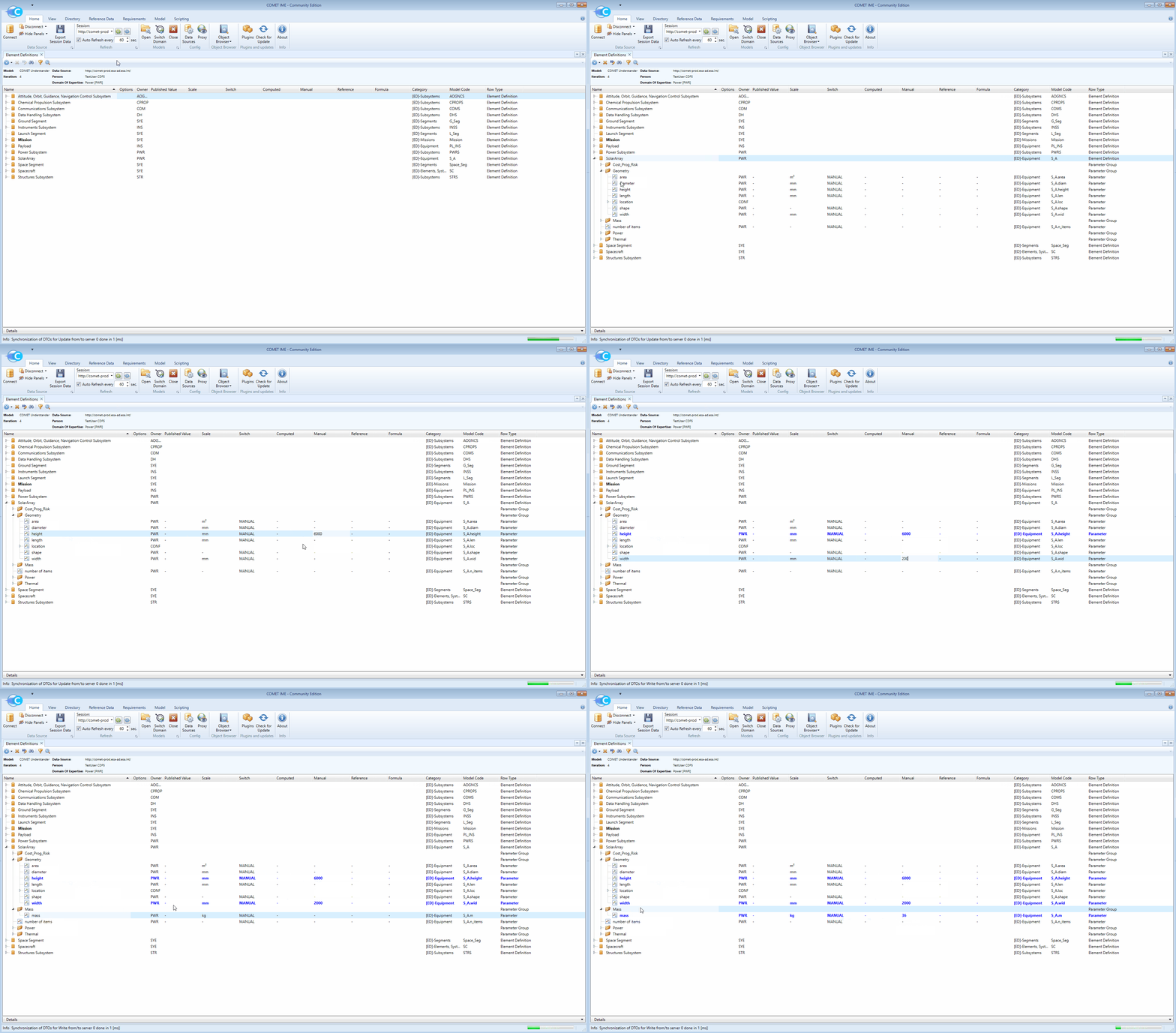
Populating equipment Parameter Values
Table of Contents
After the equipment has been created as Element Definitions, ensuring all the necessary parameters are included, it is important to start giving values to those parameters. In the scope of concurrent engineering, the values given to parameters owned by one domain can be useful for other domains and should therefore be kept up to date. At the beginning of the modelling exercise it may not be possible to provide accurate values for parameters due to the high uncertainties within the model. However, towards the end of the study, values should become more accurate as more calculations will be completed which will reduce the uncertainties within the model.
To deal with this reality, each parameter has a Manual, a Computed and a Reference field that can be filled in. In general:
Manualis for a value based on initial best guess at the beginning of the study. Later in the study, the value can also be filled with a value resulting from calculations.
Computedis for a value which resulted from an analysis or computation. This is typically closer to the final solution, as it is the result of some calculation, but is still expected to change as the overall design is iterated.
Reference: a value used for comparison that originates e.g. from a data sheet or a previous study.
⚠️ WARNING: The
Computedvalue cannot be typed into COMET directly. It can only be populated by pushing it through external tools such as the COMET Excel Plugin (see here)
-
To assign a Parameter Value to a parameter, navigate to that parameter in the Element Definitions browser and fill in the value in the appropriate slot (Manual or Reference). Make sure that the
Switchvalue is set to corresponding entry.Manual,ComputedandReferencecan all be populated with a value but, while they all remain visible to other domains, only the one indicated by theSwitchwill be published.
NOTE: It is expected that all parameters are given a value where possible.
-
When assigning values to parameters, be careful to ensure the input value is in the correct units as indicated by the
Scale. -
There are four special parameters that are often used when modelling in COMET. These are tackled below.
Maturity Margin
The maturity margin is one of the 24 standard parameters and it reflects the design maturity of the equipment. In the CDF, it should be employed as specified in the CDF Standard Margin Philosophy (only accessible within ESA VPN) and it is advised to read this document prior a CDF study.
-
In general, the parameter takes the following values:
Maturity Margin ECSS-E-ST-10-02C Product Category 5% For off-the-shelf equipment with no modifications A 10% For off-the-shelf equipment with modifications B or C 20% For newly designed and developed equipments D -
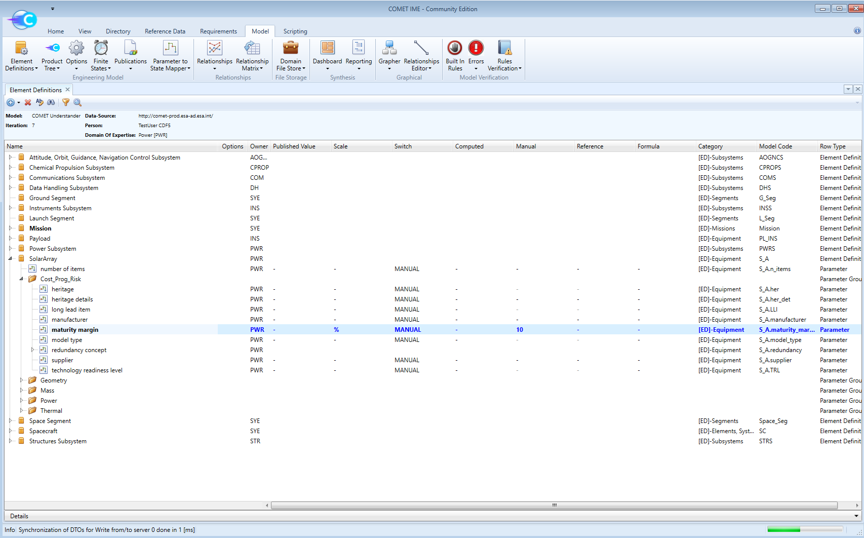
The parameter is populated normally, as any other parameter would be:

⚠️ WARNING: Do not confuse the
maturity marginwith the System Margin. Thematurity marginis populated in each equipment by the experts. The System Margin is added by the systems team to the system as a whole, on top of the maturity of each equipment
Power Duty Cycle
The power duty cycle is one of the 24 standard parameters and it is closely related to the concept of Finite States, which is tackled here. This parameter describes the percentage of time the equipment is active during a given state. It can take the following values:
| Value | Meaning |
|---|---|
| 0 ≤ power duty cycle ≤ 1 | A percentage of the time the equipment is consuming power during the given state. A value of 0 means the equipment is on Standby and does NOT mean the power consumed during the state is 0 W |
| -1 | The equipment is off for the entire duration of the state and will consume 0 W of power |
NOTE: The calculation of the
mean consumed power, which is dependant on thepower duty cycle, follows the (simplified) equation:
P_mean = [ P_on * DC + P_Stby * (1 - DC) ] * [ 1 + MM ]
where: P_mean is themean consumed power, P_on is thepower while on, DC is thepower duty cycle, P_Stby is thepower in standbyand MM is the equipmentmaturity margin.
Values for the power duty cycle are applied as they would for any other parameter.
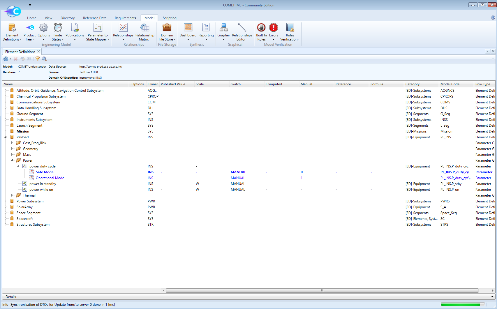
NOTE: The example of the Power expert modelling the solar array that has been used so far is not applicable here because the
power duty cycleparameter does not apply to a solar array. For this reason, in the figure below, thepower duty cyclehas been applied by the Instruments expert to the payload equipment:

Redundancy Concept
The redundancy concept is one of the 23 standard parameters and it allows redundancy to be modelled in the system. It is composed of four sub-parameters:
| Name | Value | Meaning |
|---|---|---|
| redundancy.scheme | active passive standby | hot redundancy - all units always on cold redundancy - k units on and n-k off k units on and n-k standby |
| redundancy.type | internal external | redundant units all in single package/box Only one Element Usage in COMET with n_items=1 redundant units explicitly modelled in design n Element Usages in COMET or one Element Usage with n_items>1 |
| redundancy.k | integer >= 1 | number of units needed for nominal operation |
| redundancy.n | integer > k | total number of units in the system |
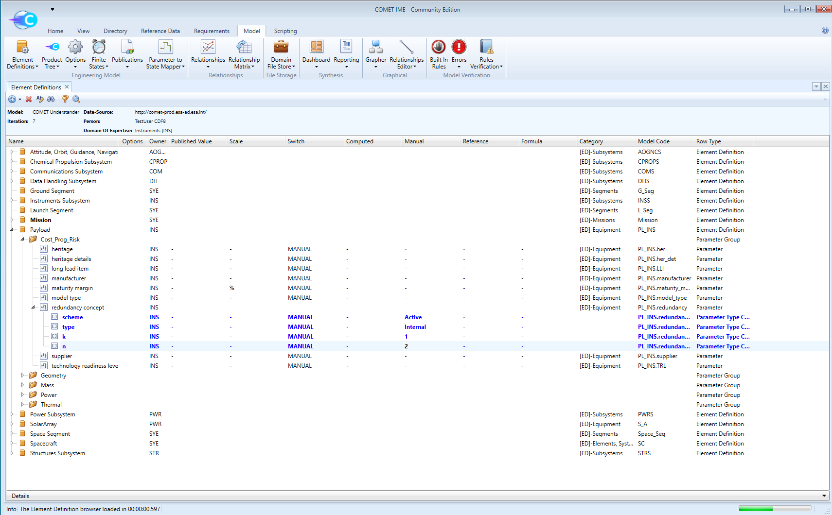
NOTE: The example of the Power expert modelling the solar array that has been used so far is not applicable here because the
redundancy conceptparameter does not apply to a solar array. For this reason, in the figure below, theredundancy concepthas been applied by the Instruments expert to the payload equipment. In this case, the payload contains two identical components internally, both of which are always on but only one of which is required for nominal operation:

NOTE: For more in-depth information on the
redundancy conceptparameter, see the advanced section
Number of Items
Finally, the parameter n_items is used to model equipment which appears multiple times in the model. For example, if 2 identical solar arrays are required on the Spacecraft, the n_items parameter can be set to 2 in the Element Definition of the solar array. The mass and power parameters will be acconuted for n times when this parameter is used.
Hide Example
This corresponds to adding values to parameters in all Element Definitions in COMET.
