STEP TAS adapter - Reference manual
Table of Contents
- Introduction
- Help Method
- Screen Definitions and Operations
- Commands and Operations
- Connecting to CDP4 Hub
- Refresh information in the Adapter
- User Settings Dialog Box
- Load a local STEP-TAS file
- Specification of Mapping Configuration
- File to Hub: define a mapping
- File to Hub: Transfer the mappings
- Retrieving a STEP-TAS file from the hub.
- The STEP-TAS File Comparison Functionality
- Publications
- Data extraction from HUB for ESATAN-TMS computation
- considering ElementUsages
- considering “OBC” Element Definition
- considering Nodal contributions from ElementUsages
- Upload CSV files on HUB
Introduction
The developed GUI relies on some components used in some other adapters (provided by the DEHP Common .NET package). These components offer all classical user interaction process like:
- Clicking on buttons
- Selecting files by selectors
- Checking check boxes
- Scrolling list
- Frame with tabs
- Right click on entries to open context menus
- …
and permit to the users to understand quickly how things can be done.
Help Method
No online help is available for the moment because all operations are done manually in the GUI. Note that some helps are available in the GUI by passing the mouse pointer at interesting location of the interface and waiting for a second, letting appear a “tooltip” at the location of the pointer to guide the user about the purpose of the underlying object, helping the user during the execution of his task.
Screen Definitions and Operations
The STEP-TAS main window, shows practically all the information the user requires, therefore a minimum screen resolution of 1280 pixels by 768 pixels. It is possible to resize the different inner panels to accommodate the view. It does not contain any window top menu, but some operations are available through context menu or by selecting tree items in the relevant panels.
Commands and Operations
Connecting to CDP4 Hub
In the Hub Data Source frame of the main window, you have to click on Connect button and fill requested information in the dialog box that will appear.
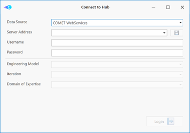 Figure 2 : Get connected to a shared Engineering Model with STEP-TAS adapter First, you will have to specify:
- Data Source
- Server address
- Username
- Password
and click on Login button. Once the connection is established, you will have to fill the second part of the dialog box by specifying:
- Engineering Model
- Iteration
- Domain of Expertise
and click on Continue button. You are now connected to the Hub Data Source.
Refresh information in the Adapter
To retrieve the last information in the Hub (for example, modifications in the Hub due to other people working on the same engineering model at the same time), you have to click on the Refresh button:
in the right Hub Data Source frame of the main window. The information from the Hub is updated in the Model, Publications, and File Store tabs.
User Settings Dialog Box
On the righthand bottom corner of the application the button opens the User Settings Dialog box.
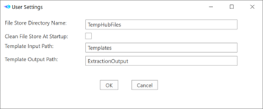 Figure 3:User settings of STEP-TAS adapter
The available user settings are:
- File Store Directory Name: This is the name of the subdirectory, located in the application directory that will be used to store the STEP-TAS files retrieved from the hub.
- Clean File Store At Startup: If selected, the content of the file store directory will be deleted when the application starts.
- Template Input Path: This is the name of the subdirectory, located in the application directory that will be used to store the default template files used by Scriban script for extraction of additional information for ESATAN-TMS computation (i.e. dissipation budget at thermal nodes)
- Template Output Path: This is the name of the subdirectory, located in the application directory where the ext files generated by Scriban scripts will be stored.
Pressing OK will save the modified user preferences.
Load a local STEP-TAS file
Click on Load STEP-TAS file of the STEP-TAS frame of the application. A new dialog box appears and you have to specify the local STEP file to load.
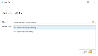 Figure 4:Load a local STEP-TAS file You can select the file by browsing the drives and subdirectories on your computer or select a file among “Recent Files” box. Then click on Open button. The file is loaded and you will then be able to visualize the general information in the Header section and the HRL tree which complete the STEP-TAS frame of the application. If when loading the file there is an active connection to a Hub Data Source, then the Mapping Configuration Manager dialog is displayed in order to select the associated mappings to be used in the current STEP-TAS file (see next section).
Specification of Mapping Configuration
In order to avoid the manual mapping of objects every time an input file is selected, the mapping can be saved on the hub under a configuration name. This supports the user by restarting from existing mapping information and he has just to specify the change/add when he performs new mappings. As this configuration is saved in the Hub, other users of the STEP AP242 adapter can access immediately as this is available. On the following picture, you can see the Mapping Configuration Manager of STEP-TAS files:
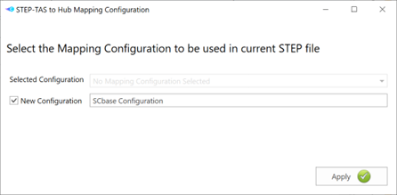 Figure 5:Defining the mapping configuration
- Selected Configuration: list of mapping configurations already available in the Hub Data Source.
- New Configuration: when checked, you have to specify the name for new one.
By clicking on Apply button the selected or a new configuration is applied to the current HLR replacing previous mapping configurations. In case of closing the dialog without applying a configuration, everything remains unchanged.
File to Hub: define a mapping
Once a local STEP file is loaded, you can start to map HLR parts to Element Definitions and/or Element Usages by performing a right-click on the part and selecting “Map [part description]” item from the context menu. Mapping data structure The STEP-TAS part data is mapped to an Element Definition or Element Usage, with a step tas reference compound parameter. If this parameter does not exist in the Element Definition it will be added at the transfer time. Note: the step tas reference parameter type is automatically created by the adapter on the Reference Data Library of the selected Engineering Model if it does not exist. The step tas reference is composed by the following parameters:
- name: the name of the STEP-TAS part.
- path: the access path of the STEP-TAS part in HLR
- side : no yet supported
- node : no yet supported (At the present time, this information is retrieved from the STEP-TAS file for further processes)
- type: the type of the STEP-TAS part
- description: the description of the STEP-TAS part
- stepid : the string id of the STEP-TAS part in the STEP-TAS file
- source: Unique Id of the FileRevision which holds the STEP-TAS file stored in the hub.
All this information will be associated to the Element Definition or Element Usages and will permit to link the right entity contained in the STEP-TAS file that will be stored on the Domain File Store. For your information, the resulting step tas reference compound parameter is seen like this
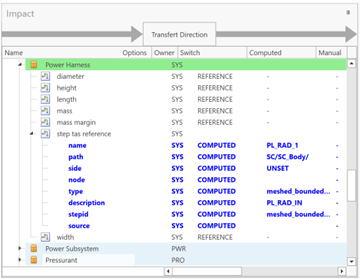 Figure 6:“step tas reference” compound parameter
in the GUI. Here the selected entity (“PL_RAD_1”) is mapped on “Power Harness” Element Definition.
Mapping configuration rules for File to hub Once a mapping is initiated by a right-click on an entity of the HLR of the STEP file, the following dialog box appears:
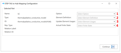 Figure 7:Mapping configuration dialog box
in which you have to enter optionally 4 fields.
- The Option serves to two purposes. When selected, only Element Usages include in the selected option are available. Also, if the selected Element Definition contains a step tas reference parameter which is option dependent, then selected Option will be used to set the values. A warning message will appear in case the step tas reference parameter is “Option Dependent” and no Option was selected. To make a step tas reference parameter “Option Dependent”, you can use COMET-CE.
- Select one Element Definition. If no Element Definition is specified, a new Element Definition will be created with a name specified by the user.
- Select one or several Element Usages. When selecting Element Usages of one Element Definition, all the overridden step tas reference parameters will be updated. If one selected Element Usage has its step tas reference parameter that is not set as “Overridden”, the selected Element Definition will be impacted by the mapping. The “Overridden” state of a parameter can be for example set in COMET-CE.
- Select the Actual Finite State to consider when the step tas reference parameter is “State Dependent”. To set a step tas reference parameter as “State Dependent”, you can again proceed with COMET-CE. For more details, please consult COMET-CE documentation.
Notes:
- A mapping operation can be done several times before transfer of information to the Hub.
- Once a mapping is defined, the impacted Element Definitions and Element Usages will be highlighted in green in the Impact frame at the center of the main window of the STEP-TAS Adapter (see Figure 6).
File to Hub: Transfer the mappings
Once all the requested mappings are set/added for the selected STEP-TAS file, the user can decide to transfer them to the Hub. But before doing the transfer, the user can decide to not transfer some of the mappings. By default, the mappings are highlighted in green in the Impact view. If you click on any of them, it will change to yellow and will not be transferred. You can click on yellow ones to make them green again so that they are finally transferred. There is context menu that will allow to select/unselect all of them in one operation.
For example, in the next picture, as the power harness is yellow, the related mapping will not be transferred.
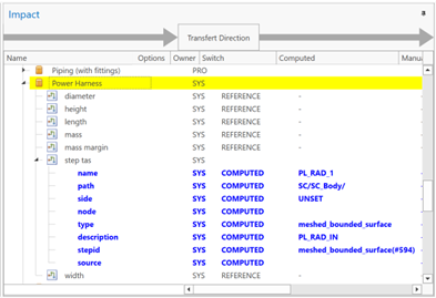 Figure 8:The entry highlighted in yellow will not be transferred
Once all the mappings to transfer have been decided, the user can launch the transfer. To proceed, he has to click on Transfer button in the main window. Then, the user is invited to introduce a “Justification”:
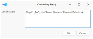 Figure 9:Add a “Justification” for mapping transfer operation in order to create a log entry in the Hub in order to help in the monitoring of reasons for changes.
Retrieving a STEP-TAS file from the hub.
This functionality just permits to retrieve a STEP-TAS file from the Hub. From the Hub Data Source frame, there are 2 possibilities:
- From File Store tab, select the file and click on “Download As…”
OR
- From the Model tab, retrieve directly the STEP-TAS file containing the STEP-TAS description of an Element on the Hub starting from the Element itself (by a right click)
Mapping a STEP-TAS file from the hub to a local STEP-TAS file is not possible in this Adapter because modifying an existing STEP-TAS file is not an obvious task.
The STEP-TAS File Comparison Functionality
It is possible to do a High Level comparison between the loaded step file and the one selected from the hub.
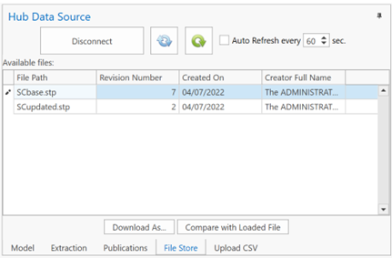 Figure 10:The list of STEP-TAS files on the Hub Once you have loaded a file (using Load STEP-TAS file), you can select a file in the Hub Data Source File Store. After that you can trigger the comparison between the two files using the Compare with Loaded File button. It will then display a dialog box similar to this one:
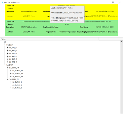 Figure 11:STEP-TAS files difference viewer (The 2 files are identical here)
The Loaded File content is highlighted in yellow. The HUB file content is highlighted in green. The part of High Level Representation that is similar in both files is displayed in black (not highlight). Please note that the HLR representation in only based on names. If you have two files that contains similar data with only the root of the structure bearing a different name, they will be considered as being completely different. When the files are considered being different, you will see two coloured trees.
Publications
With the STEP-TAS adapter, you can visualize current publications by selecting Publications tab in Hub Data Source frame on the right part of the main window.
Data extraction from HUB for ESATAN-TMS computation
Once the adapter is connected to an Engineering Model on the hub and a related local STEP-TAS file is loaded, this functionality is accessible through the Extraction tab in the Hub Data Source frame.
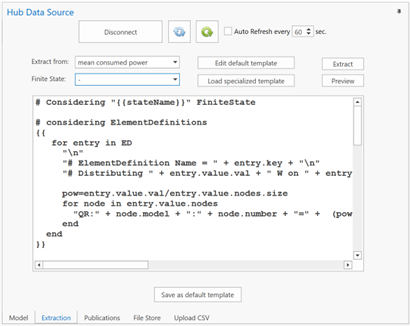 Figure 12:The Extraction tab for the generation of additional input information for ESATAN computation For all Element Definition that have a step tas reference compound parameter (then a reference to the STEP-TAS file), the possible SimpleQuantityKind parameters list will be extracted and exposed to the user. Then, the user has to select in Extract From the type of parameter he would like to process to generate an input .ext file for the ESATAN solver. Depending on his selection, the user will be invited to select a Finite State of interest (if the property has Finite States for some Element Definition ). By default, according to the selected parameter type, a default Scriban script will be processed to generate the adequate .ext input file for ESATAN-TMS. However, if the default script is not adequate, the user can edit (by clicking on Edit default template) and modify the default script or load a completely new one with Load specialized template button (and eventually save it as the default script by clicking on Save as default template). To process the script and generate inputs for ESATAN, there is 2 possibilities:
- Click on Extract : this action will generate a steptas.txt file containing the result of the generation. This file will be generated inside Template Output Path directory (defined in User preferences).
- Click on Preview : this action will open a new windows to preview the results of the generation.
Note for Scriban scripts: Concerning model objects that are currently exposed in the Scriban script (and then accessible through the template), we have:
- stateName : the string containing the name of the selected Finite State
- ED: a dictionary containing information of Element Definition with
- key: The name of the related Element Definition
- value: Part of the information stored in the related Element Definition with
- val : the value of the selected property for the extraction
- name: the name of the linked STEP-TAS entity
- nodes : the “node data” list of the linked STEP-TAS entity. For each “node data”, we have:
- number: the node id
- model: the associated model name to the node
- EU: a dictionary containing information of Element Usage with
- key: The name of the related Element Usage
- value: Part of the information stored in the related Element Usage with
- val : the value of the selected property for the extraction
- name: the name of the linked STEP-TAS entity
- nodes : the “node data” list of the linked STEP-TAS entity. For each “node data”, we have:
- number: the node id
- model : the associated model name to the node
Sometimes, it can happen that several entities on the hub have the same related nodes in the STEP-TAS file. In this case, it is better to use other data information that are also accessible through the Scriban script. This approach is more robust and can also be used if no entities on the hub have the same related nodes in the STEP-TAS file.
- NodalFromED: a dictionary containing nodal contribution from Element Definition with
- key: The complete node identification string (“modelName:nodeId”)
- value: Nodal data with - val : the value of the selected property for the extraction (sum of contribution coming from all Element Definition) - name : the name of the related entity in the STEP-TAS file
- NodalFromEU: a dictionary containing nodal contribution from Element Usage with
- key: The complete node identification string (“modelName:nodeId”)
- value: Nodal data with
- val : the value of the selected property for the extraction (sum of contribution coming from all Element Usage)
- name : the name of the related entity in the STEP-TAS file
considering ElementUsages
Below, you will find 3 illustrative examples for Scriban scripts:
Example 1:
As a first illustrative example, you will find below a Scriban script that will generate heat power at nodes for an ESATAN model by “scanning” all Element Usage (EU)
for entry in EU
  "\n"
  "# ElementUsage Name = " + entry.key + "\n"
  "# Distributing " + entry.value.val + " W on " + entry.value.name + " (" + entry.value.nodes.size + " node(s))\n"
  pow=entry.value.val/entry.value.nodes.size
  for node in entry.value.nodes
    "QR:" + node.model + ":" + node.number + "=" + (pow | math.format "E") + "\n"
  end
end
considering “OBC” Element Definition
Example 2:
Another example is given below if the user wants to address a directly an Element Definition by the knowledge of its name (here “OBC” for example). Since ED is a Dictionnary, we can use the [ ] operator.
"\n"
data = ED["OBC"]
"# Distributing " + data.val + " W on OBC (" + data.nodes.size + " node(s))\n"
pow=data.val/data.nodes.size
for node in data.nodes
  "QR:" + node.model + ":" + node.number + "=" + (pow | math.format "E") + "\n"
end
considering Nodal contributions from ElementUsages
Example 3:
For the last example example, you will find below a Scriban script that will generate heat power at nodes for an ESATAN model using NodalFromEU information
for entry in EU
  "# ElementUsage Name = " + entry.key + " --> Distributing " + entry.value.val + " W on " + entry.value.name + " (" + entry.value.nodes.size + " node(s))\n"
end
for entry in NodalFromEU
    "QR:" + entry.key + "=" + (entry.value.val | math.format "E") + "\n"
end
Upload CSV files on HUB
Once additional input files are generated by “Extraction” feature for ESATAN computation, the user can perform the thermal simulation. Here, we assume that some CSV files with nodal temperature results at nodes are generated by ESATAN. Now, the main objective consists in uploading the temperature results on the hub inside Element Definitions / Element Usages having reference to the nodes referenced in the CSV File. This functionality is accessible through the Upload CSV tab in the Hub Data Source frame.
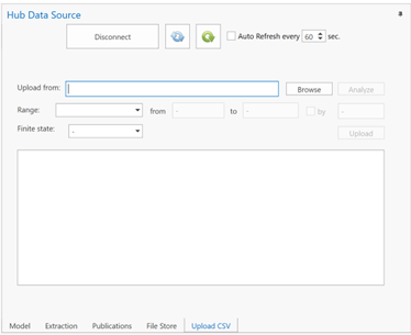 Figure 13:”Upload CSV” feature
The user has to select first the CSV file to upload by clicking on Browse. Then, the user has to analyze the selected file by clicking on Analyze. The user will have to select what kind of information he would like to submit to the hub. Here is the 3 possibilities in Range combo list :
- All XXX times: all the timesteps inside the CSV file will be considered (XXX is the number of timesteps in the file)
-
Time range : the user can here specify the time range (From X s to Y s , with an eventual resampling specified in by
- Simple time : on single temperature will be upload to the hub at one single timestep specified in at

- If there are Finite States defined in the Engineering model on the hub, the user can select in which Finite State he would like to upload the temperature results on the hub inside the Finite state combo-list.
Once the range is specified (and the Finite State eventually selected), the user can click on Upload. At his level, the adapter will add sampled temperature, minimum temperature and maximum temperature parameters) to Element Definition / Element Usage that have nodes referenced in the CSV file.
- sampled temperature: It is a SampledFunctionParameter that will contain the time series of the arithmetic mean temperature on related component (the mean is done one the related nodes)
- minimum temperature: It is a unique value extracted for the considered time range
- maximum temperature: It is a unique value extracted for the considered time range Note: In the lower part of the Extraction tab, there is a text output that can report useful information related to the upload that was performed.