Adding equipment to the system
Table of Contents
Until this point, equipment has been created with all required parameters included and those parameters have had values assigned. This is the equivalent of composing the blueprints of the equipment and storing them as a catalogue of items that can be used in the model. To start modelling the system itself, relationships must be created between Element Definitions. This is done through the Product Tree view. To open the Product Tree view:
-
Navigate to the Model tab.
- Click on
Product Treeand select the available iteration.NOTE: If more than one Option is defined in the Study Model, you will be prompted to choose which options you wish to work on. Study Models for new CDF studies will typically not have Options defined at first.
- Place the Product Tree view next to the Element Definition browser.
While the Element Definition browser displays all Element Defintions on the same level, the Product Tree view provides a tree-like breakdown of the model, based on the relationships between Element Definitions. The standard tree structure for a CDF study is:
- Mission
- Ground Segment
- Launch Segment
- Space Segment
- Spacecraft
- Subsystem 1
- Subsystem 2
- …
- Equipment 1
- Equipment 2
- …
- Spacecraft
Notice that, for each “entry” in the Product Tree view, an Element Definition is defined in the Element Definitions browser. The top element in the Product Tree view, the Mission, is highlighted in bold in the Element Definitions browser.
The mission is modelled by nesting Element Definitons into one another, starting from the Mission and going down to equipment level. By dragging and dropping Element Definitions from the Element Definitions browser onto the Product Tree view, they are added to the system (and thus also to the Product Tree view) and Element Usages are created. Element Usages are instances of Element Definitons that are being used in the system. Multiple Element Usages can be created from a single Element Definition. In COMET Element Definitons are represented with the icon ![]() and Element Usages with the icon
and Element Usages with the icon ![]() .
.
In the example followed so far, the blueprint for the solar array (Element Definition ![]() ) has been made and that needs to become a part of the spacecraft (Element Definition
) has been made and that needs to become a part of the spacecraft (Element Definition ![]() ). By dragging the solar array from the Element Definitions browser onto the spacecraft in the Product Tree view, the solar array becomes appended to the spacecraft as an Element Usage
). By dragging the solar array from the Element Definitions browser onto the spacecraft in the Product Tree view, the solar array becomes appended to the spacecraft as an Element Usage ![]() :
:
⚠️ WARNING: Do NOT drag equipment into the subsystem Element Definitions. These are functional representation of each subsystem as described here. Always, only drag equipment into the spacecraft/platform (the name of this Element Definition will be indicated by the Assistant Systems Engineer)
⚠️ WARNING: Do NOT nest equipment. Even if one equipment is a sub-component of another equipment, all equipment Element Usages must be one level deep under the spacecraft/platform (the name of this Element Definition will be indicated by the Assistant Systems Engineer)
NOTE: Only Element Usages, which make up the model, will be counted in the budgets (mass budget, power budget, etc). If an equipment is defined (as an Element Definition in the Element Definitions browser) but not used (as an Element Usage in the Product Tree view) it is not a part of the system
⚠️ WARNING: When changing the name of an Element Definition in the Element Definitions browser, make sure to also change the name of any Element Usage in the Product Tree view.
Hide Example
This corresponds to making Element Usages by dragging Element Definitions into the Spacecraft in COMET.
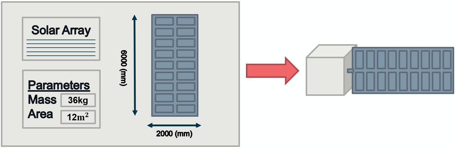
This gets combined with the equipment made by other domain experts to form the model of the completed system.

Note: in this figure different colors indicate different ownership.